04.09.2026 by Viktor Siebert
CNC Failure Caused by a Mitsubishi MDS-C1-V1-35-N Without Function: Defective Internal Power Supply Stops the Servo Axis
Machine Downtime Caused by a Failed Mitsubishi Servo Drive
For the operator, the failure caused an immediate standstill of the affected machine function. Because the drive amplifier no longer powered up, no regular alarm code was available. The fault diagnosis therefore had to begin directly inside the unit.
The Mitsubishi MDS-C1-V1-35-N Servo Drive Unit arrived at our workshop completely without function. The unit no longer started and did not reach operational readiness. As a result, the associated CNC axis could not be enabled.
According to the nameplate, this is a Mitsubishi Electric Servo Drive Unit with a specified output of 3.5 kW. The unit at hand was manufactured in May 2019 and has hardware version Q and software version A4/A5.
Initial Diagnosis
The examination began with a visual inspection of the housing, connections and internal assemblies. The basic supply paths were then checked.
According to the available assembly documentation, the Mitsubishi MDS-C1-V1-35-N consists of three main sections:
- Control PCB
- Power PCB
- Power section
Because the unit showed no function whatsoever, the initial focus was on the internal power supply and the supply to the control PCB. A defect in this area can prevent the control, signal processing, communication and monitoring functions from starting at all.
In this unit, the internal supply voltages could no longer be established correctly. As a result, the entire servo drive remained inoperative.
Actual Cause of the Fault
The electrical examination confirmed a defect within the internal power supply.
The resulting chain of faults was clear:
- The internal power supply no longer provided the required supply voltages correctly.
- The control PCB could not initialise properly.
- The internal monitoring and communication functions remained inactive.
- The servo drive did not reach an operational state.
- A normal alarm display was not possible because the unit did not start.
- The CNC control could not put the drive amplifier into operation.
The fault was therefore not automatically located in the power section, the connected motor or the motor feedback system. Only the systematic examination of the internal supply made it possible to identify the power supply as the actual cause of the complete unit failure.
Repair Measures
After the fault had been located, the affected power supply section was repaired at component level. Only those components that had actually been identified as defective were replaced.
The repair included:
- Disassembly of the Mitsubishi servo drive
- Visual inspection of the control and power assemblies
- Examination of the internal power supply
- Measurement and localisation of the missing supply
- Testing of the affected circuit areas
- Replacement of the defective power supply components
- Inspection and reworking of the repaired solder joints
- Cleaning of the assemblies
- Testing for short circuits and impermissible current consumption
- Controlled recommissioning
- Repeated power-up and functional tests
Once the power supply was operating stably again, the control PCB and the remaining unit functions were able to start up in a controlled manner.
Final Testing and Return Shipment
After the repair, the MDS-C1-V1-35-N was recommissioned step by step. Particular attention was paid to the unit start-up and the stability of the repaired power supply.
The final inspection included:
- Controlled power-up test
- Verification of the initialisation
- Repeated power-on and power-off cycles
- Monitoring of the internal power supply
- Inspection for unusual heating
- Functional testing of the internal assemblies
- Final visual inspection
- Documentation of the repair result
After passing the tests, the Mitsubishi servo drive was prepared for return shipment. The existing unit could continue to be used, meaning that no conversion of the machine to a different drive system was required.
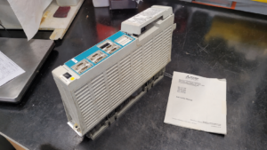
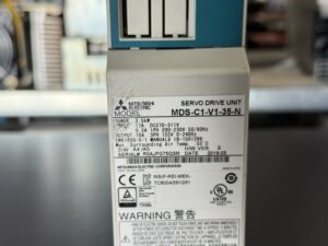
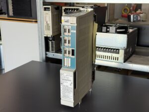
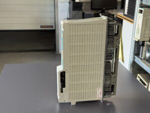
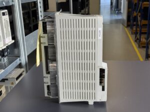
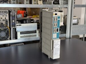
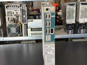
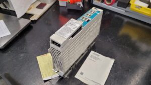
To mentioned Mitsubishi Drive: Mitsubishi MDS-C1-V1-35-N Servo Drive
More details about our Mitsubishi repair services can be found here:
Mitsubishi drive Repair by Industrypart
📞 Feel free to contact us with any questions about your Mitsubishi drive technology.
Our expert team is happy to help!
Technical Data of the Mitsubishi MDS-C1-V1-35-N
| Feature | Nameplate information |
|---|
| Manufacturer | Mitsubishi Electric Corporation |
| Device designation | Servo Drive Unit |
| Model | MDS-C1-V1-35-N |
| Alternative spelling | MDSC1V135N |
| Rated output | 3.5 kW |
| DC link input | 17 A, DC 270 to 311 V |
| Control input | 0.2 A, single-phase, AC 200 to 230 V |
| Input frequency | 50/60 Hz |
| Output current | 19 A |
| Output | Three-phase, AC 155 V |
| Output frequency | 0 to 240 Hz |
| Software version | A4/A5 |
| Hardware version | Q |
| Manufacturing date | 2019-05 |
| Standard | EN 61800-5-1 |
| Manual reference according to nameplate | IB-1501296 |
| Country of manufacture | Japan |
| Maximum surrounding air temperature | 55 °C |
Safety Information From the Nameplate
The unit contains capacitors that can retain dangerous electrical voltage after the power has been switched off. According to the warning on the nameplate, the capacitor discharge time is approximately 15 minutes.
The unit and its wiring must therefore not be touched or worked on immediately after switching off the power. Before any work is performed, the absence of voltage and the discharge condition must be checked professionally.
The MDS-C1 troubleshooting documentation also states that the system uses large-capacity electrolytic capacitors. As long as the CHARGE indicator on the associated power supply system is illuminated, dangerous voltage may still be present.
Operating Conditions
| Operating condition | Documented information |
|---|
| Maximum surrounding air temperature | 55 °C |
| Power supply monitoring | Check ambient temperature, cooling and grounding in the event of faults |
| Cooling fins | Keep free from cutting oil, dust and heavy deposits |
| Fan | Check operation in the event of thermal problems |
| Grounding | Proper grounding required |
| Electrical interference | Check for electrical noise and problematic peripheral devices |
The troubleshooting manual specifically identifies excessive ambient temperature, a stopped fan, contaminated cooling fins, inadequate grounding and electrical interference as relevant points during fault diagnosis.
Components of the Mitsubishi MDS-C1-V1-35-N
| Assembly | Designation on the PCB | Quantity | Function |
|---|
| Control PCB | RK112A-21 or BN634A980G51 B | 1 | Control, signal processing, communication and monitoring |
| Power PCB | RL122B-V1 / BN638A153G51 A | 1 | Control and connection to the power section |
| Power section | Power section | 1 | Generation of the controlled three-phase motor output |
The designations were taken directly from the available assembly overview. They must not be applied generally to every hardware version in the entire MDS-C1 series.
Interaction With Other Devices
According to the troubleshooting documentation, the MDS-C1 system operates within a CNC servo system together with other components. These may include:
- CNC control
- MDS-C1-CV Power Supply Unit
- Mitsubishi servomotor
- Motor-side high-speed serial detector
- Machine-side position detector
- Absolute or relative position measuring systems
- Detector cable and motor power cable
- Communication connections between the CNC and drive
- MDS-B-HR Interface Unit, where applicable
- Battery unit for absolute position systems
Actual compatibility depends on the machine, control, motor, feedback system, parameterisation and hardware version. A replacement must not be selected solely on the basis of similar connections or externally comparable model numbers.
Functional Description
The Mitsubishi MDS-C1-V1-35-N is a Servo Drive Unit for the controlled operation of a CNC servo axis. The unit processes the movement commands from the CNC control and drives the connected servomotor accordingly.
The nameplate specifies a three-phase output of 155 V, 19 A and a frequency range of 0 to 240 Hz. The specified unit output is 3.5 kW.
For position and speed control, the system processes the signals from the connected motor feedback system. Depending on the machine configuration, additional machine-side measuring systems may also be integrated.
The internal control monitors, among other things:
- Motor current
- Overload
- Overspeed
- Power section
- Motor temperature
- Position deviation
- Feedback signals
- Communication with the CNC
- Parameters
- Internal memory and processor functions
The internal power supply provides the electronic circuits required for these functions. In this repair case, its failure prevented the entire servo drive from initialising.
Reset Methods for MDS-C1 Alarm Messages
| Abbreviation | Meaning |
|---|
| PR | Reset by switching off the NC power supply |
| AR | Reset by switching off the servo drive power supply |
| NR | Reset according to the NC or system response after eliminating the cause |
| Warning | The servo remains switched on for correspondingly marked warnings |
A reset must only be performed after the cause of the fault has been checked and eliminated. Recurring alarms should not simply be reset repeatedly.
Alarm and Fault Codes
| Alarm | Fault name | Meaning | Reset | Measure |
|---|
| 12 | Memory error | Error in the memory or during the drive self-check | AR | Check repeatability, ambient temperature, grounding and electrical interference; examine the drive |
| 13 | Software processing error | Software processing was not completed within the specified time | PR | Check software version and environmental conditions |
| 14 | Software processing error 2 | Current control loop processing was not completed within the specified time | PR | Check software version, temperature, grounding and electrical interference |
| 17 | A/D converter error | Error in the A/D converter for current detection | PR | Check repeatability and environmental conditions |
| 18 | Initial communication error | No initial communication with the motor-side high-speed serial detector | PR | Check parameter SV025, connectors, feedback cable and detector |
| 21 | No signal 2 | A-, B- or Z-phase error detected in the closed-loop system | PR | Check parameterisation, connectors, cables, drive and detector |
| 25 | Absolute position lost | Supply to the absolute position detector was interrupted; the absolute position can no longer be guaranteed | AR | Check battery, cables and connectors; carry out zero-point return |
| 31 | Overspeed | Motor speed exceeded the permissible speed | PR | Check wiring, parameters, traverse speed and acceleration time |
| 32 | Power module error | The inverter IPM detected an overcurrent | PR | Check U, V and W cables, ground fault, motor, parameters, feedback cable and drive |
| 34 | NC communication CRC error | Error in the data transmitted from the CNC to the drive | PR | Check communication connectors, cables and software versions |
| 35 | NC communication data error | Error in the movement data transmitted by the CNC | PR | Carry out the same measures as for alarm 34 |
| 36 | NC communication error | Communication between the CNC and drive was interrupted | PR | Check the communication connection and cable |
| 37 | Initial parameter error | Invalid parameter detected when the CNC was switched on | PR | Check and correct the displayed parameter on the CNC diagnostic screen |
| 38 | NC communication protocol error 1 | Error in the communication frame transmitted by the CNC | PR | Check communication connections and system software |
| 39 | NC communication protocol error 2 | Error in the transmitted axis information | PR | Check axis information and communication |
| 3A | Overcurrent | Excessive motor current detected | PR | Carry out the measures specified for alarm 32 |
| 3B | Power module error, overheat | IPM reports an excessive temperature | PR | Check fan, cooling fins, ambient temperature, grounding and electrical interference |
| 42 | Feedback error 1 | Feedback pulse was lost or a Z-phase error was detected | PR | Check detector, connectors and feedback cable |
| 43 | Feedback error 2 | Excessive deviation between motor-side and machine-side feedback | PR | Check measuring systems, cables, parameters and drive |
| 46 | Motor overheat | Motor or thermal protection in the feedback system reports an excessive temperature | NR | Check load, motor temperature, thermal contact, cable and detector |
| 50 | Overload 1 | Load value calculated from the motor current reached the configured overload threshold | NR | Check parameter SV022, operating pattern, motor temperature and control |
| 51 | Overload 2 | A current command of at least 95 percent of the drive’s maximum performance was present for at least one second | NR | Check supply, motor current, mechanical system and operating pattern |
| 52 | Excessive error 1 | Position deviation with Servo ON exceeded the configured limit | NR | Check parameters, mechanical system, brake, motor power and feedback |
| 53 | Excessive error 2 | Position deviation with Servo OFF exceeded the SV026 limit | NR | Check machine movement, brake, communication and feedback |
| 54 | Excessive error 3 | No motor current flowed when excessive error alarm 1 was detected | NR | Check PN supply, MDS-C1-CV, DC link wiring and motor cables |
| 58 | Collision detection 0 | Collision monitoring responded during G0 or rapid traverse | NR | Check machine, parameter SV060, current limit and acceleration |
| 59 | Collision detection 1 | Collision monitoring responded during G1 or cutting feed | NR | Check collision, parameters, gain and detection level |
| 5A | Collision detection 2 | Collision monitoring type 2 was triggered | NR | Carry out the measures specified for alarm 58 |
| 6F | Power supply alarm | Power supply not connected or fault detected in the converter section | AR | Check Power Supply Unit and DC link supply |
| 7F | Amplifier power reset request | Error during control mode change or possible EEPROM error | AR | Switch the power supply back on; examine the drive if the alarm recurs |
| 88 | Watchdog | Servo drive software process was not executed within the specified time | AR | Check software version, environment, grounding and drive |
| 9F | Battery voltage drop | Battery voltage of the absolute position system is too low | Warning | Check the battery voltage and replace the battery |
| E1 | Overload warning | 80 percent of the overload alarm 1 threshold has been reached | Warning | Check load and motor temperature; reduce the operating pattern |
| E3 | Absolute position counter warning | Deviation between absolute and relative position detected | Warning | Check battery, carry out zero-point return and restart the system |
| E4 | Parameter error warning | Parameter outside the permissible setting range | Warning | Correct the parameter according to the adjustment instructions |
| E7 | NC emergency stop | CNC is in the emergency stop state or another axis is reporting an alarm | Warning | Check the emergency stop state and alarms from other axes |
Classification of the Fault in This Repair Case
No alarm code was displayed by the Mitsubishi MDS-C1-V1-35-N submitted for repair. The unit remained completely inoperative because of the defective internal power supply.
The fault therefore differs from alarm 6F. According to the MDS-C1 documentation, this alarm indicates a detected fault in the system power supply or converter section. In the unit examined here, however, the internal electronics could not start sufficiently to issue a regular alarm.
Preventive Measures
- Check the control cabinet temperature regularly
- Inspect fans and airflow
- Keep cooling fins free from dust and cutting oil
- Maintain filter mats
- Check grounding and equipotential bonding
- Check communication and feedback connectors for secure seating
- Document sporadic start-up problems
- Avoid repeatedly switching on an obviously defective drive
- Observe the specified capacitor discharge time after switching off the power
Conclusion
The Mitsubishi MDS-C1-V1-35-N with an output of 3.5 kW arrived at our workshop completely without function. The cause was a defect in the internal power supply. As a result, the control and monitoring circuits were no longer supplied correctly and the servo drive could not complete its initialisation.
After repairing the affected power supply section, the unit started correctly again. Repeated power-up and functional tests confirmed stable operation.
This case shows that a completely failed Mitsubishi servo amplifier does not automatically have a defective power section or servomotor. A structured examination of the internal power supply is essential for this type of fault.