23.10.2026 by Viktor Siebert
Mitsubishi MDS-C1-SPM-185: Repair following Alarm 32
Mitsubishi MDS-C1-SPM-185: power-stage repair following Alarm 32
This Mitsubishi spindle drive arrived at industrypart with Alarm 32. Our inspection confirmed a failed transistor module and several burnt components in the power output stage. We repaired the stage, carried out a preventive overhaul and subsequently checked the unit on our test bench. The following report distinguishes these workshop findings from general diagnostic guidance.
Technical data from the nameplate
| Parameter | Value |
|---|
| Manufacturer / Hersteller | Mitsubishi Electric |
| Type / Typ | MDS-C1-SPM-185, Spindle Drive Unit |
| Power / Leistung | 18.5 kW |
| DC input / DC-Eingang | 270–311 V DC; 76 A |
| Auxiliary input / Hilfsversorgung | 0.2 A; 1 PH; 200 / 200–230 V; 50/60 Hz |
| Output / Ausgang | 63 A; 3 PH; 200 V; 0–833 Hz |
| Hardware / Software | J / BND553W003A4 |
| Serial / Seriennummer | JBALRG2477D |
| Date marking / Datumskennzeichnung | 04/04 |
| Manual / Handbuch | BNP-C3000 |
| Standard marking / Normkennzeichnung | EN50178 |
These are nameplate ratings, not measurements from our test. The 0–833 Hz output range is an electrical frequency specification, not a direct spindle-speed rating. Mechanical speed limits depend on the motor, pole count, transmission and machine configuration. The rated output current is not a documented short-term peak current.
Application, compatibility and signal paths
The unit is a spindle drive in the Mitsubishi MDS-C1 system. It receives energy through the DC link and uses a transistor inverter to produce the three-phase motor supply. The separate auxiliary supply serves the control functions. NC commands and motor feedback form part of the control loop: the drive compares requested and actual operation and adjusts the motor current. A fault in the switching stage can therefore interrupt torque generation and trigger protection.
The manufacturer troubleshooting reference identifies CN1A/CN1B for NC communication and PLG/encoder feedback paths for spindle operation. Connector assignment, detector type and optional orientation or C-axis functions must be checked against the actual machine documentation. No particular machine model or motor pairing is documented for this repair. Matching power alone does not establish interchangeability: full model suffix, voltage class, hardware/software, feedback configuration and the approved parameter set all matter.
Assemblies and confirmed findings
| Assembly | Function and finding |
|---|
| Transistor module | Switches motor power. Failure confirmed during inspection. |
| Power output stage | Several burnt components confirmed. Stage repaired. |
| Control/current sensing | Processes commands and feedback. No separate board failure or board part number documented. |
| Cooling system | Removes power losses. Fan replacement or a cooling fault was not reported for this case. |
What Alarm 32 means
The MDS-C1 troubleshooting chapter describes Alarm 32 as activation of the power module overcurrent protection. This identifies the protection mechanism, not the root cause. The manual distinguishes occurrence before and after READY ON. It also calls for checking motor-type parameters, control-loop settings, motor power wiring and the motor. In this case the transistor-module and output-stage damage was confirmed by inspection; an external initiating cause is not established by the available record.
Diagnostic separation of drive, cable and motor
A useful fault record includes the exact display, the operating phase, repeatability and any recent work on the machine. An alarm before enable differs diagnostically from a trip during acceleration or machining. The manufacturer names SP034, SP040 and SP257–SP384 when checking the spindle motor configuration. These references are diagnostic context, not a recommendation to change settings blindly. First compare with the machine manufacturer’s approved data.
The power cable and motor must be assessed separately so a short circuit or earth fault outside the drive is not mistaken for an isolated electronics fault. Insulation testing requires the correct disconnection of electronic components and the prescribed test method. Feedback faults, excessive mechanical load and cooling problems are separate diagnostic branches. None of these external faults is claimed as a finding in this repair. Electrical investigation belongs in qualified hands with the unit safely isolated and stored DC-link energy discharged according to the manufacturer procedure.
Selected relevant spindle-drive alarms
Only Alarm 32 was reported for this unit. The reference below helps distinguish other fault groups; it is not a list of faults found during the repair. It uses the spindle-applicable entries of the MDS-C1 troubleshooting chapter. Power-supply alarms and servo-only entries are not mixed into this table. Availability of optional functions depends on configuration.
| Code | Meaning | Diagnostic context | Page |
|---|
| 12 | Memory/self-test | Check internal electronics and power-on behaviour. | 6-11 |
| 13 / 14 | Software processing | Processing deadline exceeded; consider software revision and environment. | 6-11 |
| 16 | Magnetic pole position | Initial pole detection incomplete; check PLG adjustment and matching parameters. | 6-11 |
| 17 | Current feedback A/D conversion | Investigate current sensing, electronics and interference. | 6-12 |
| 20 | Motor detector signal missing | Check PLG Z phase or A/B signals during adjustment. | 6-14 |
| 21 | Machine-side detector signal missing | For the spindle, check encoder, connections and orientation configuration. | 6-15 |
| 23 | Speed deviation during acceleration | Command and feedback differ too long; investigate wiring, load and parameters. | 6-15 |
| 31 | Overspeed | Permissible speed exceeded; check command, feedback and overshoot. | 6-18 |
| 32 | Power module overcurrent protection | Reported in this case. Distinguish internal power-stage damage from faults in the external motor circuit. | 6-18 |
| 34 / 36 | NC communication data / interruption | Check bus connections, contacts, termination and interference. | 6-19 |
| 37 | Initial parameter error | The NC identifies the parameter; compare the approved parameter set. | 6-20 |
| 38 / 39 | NC protocol error | Invalid frame or axis information; investigate the communication path. | 6-20 |
| 3B | Power module overtemperature | Check fan, cooling fins, cabinet temperature and airflow. | 6-21 |
| 3D | Spindle speed lock | Insufficient speed despite maximum torque command; investigate supply, wiring and mechanics. | 6-22 |
| 3E | Spindle speed overrun | Speed feedback does not match command; check motor assignment and control loop. | 6-22 |
| 3F | Speed deviation at constant speed | Distinguish excessive load, mechanical locking, motor and drive faults. | 6-23 |
| 42 / 43 | PLG/encoder feedback error | Check signals, connectors, cables and electromagnetic interference. | 6-23–6-24 |
Repair and test-bench check
We repaired the affected power output stage and performed a preventive overhaul of the unit. A damaged module and burnt neighbouring parts make assessment of the complete affected circuit important. The documented scope does not identify individual replacement part numbers, so these are not inferred. Following the work, the drive was checked on our own test bench. The supplied original recording documents part of that check. It does not establish a specific test load, test duration or subsequent machine operation.
Preventive measures for operation
Keep cooling passages and cabinet filters clear and check fan operation during planned maintenance. Reduced heat removal increases thermal stress on power electronics. Check cable routing, strain relief, connector condition and protection against coolant contamination. Record recurring alarms with operating conditions instead of repeatedly resetting them. Retain a backup of the approved parameters and full unit identification before replacement. These measures support diagnosis and reliability; they are recommendations, not additional work claimed for this case.
Sources and scope
Nameplate and supplied workshop record for this individual unit. Manufacturer reference: Mitsubishi MDS-C1 Series, chapter 6, troubleshooting, printed pages 6-11–6-24. Alarm 32: page 6-18. The supplied extract does not show a revision identifier. The nameplate separately identifies manual BNP-C3000. Machine-specific wiring and approved parameters take precedence for the installed configuration.
Video: repair and original test footage
Before and after repair
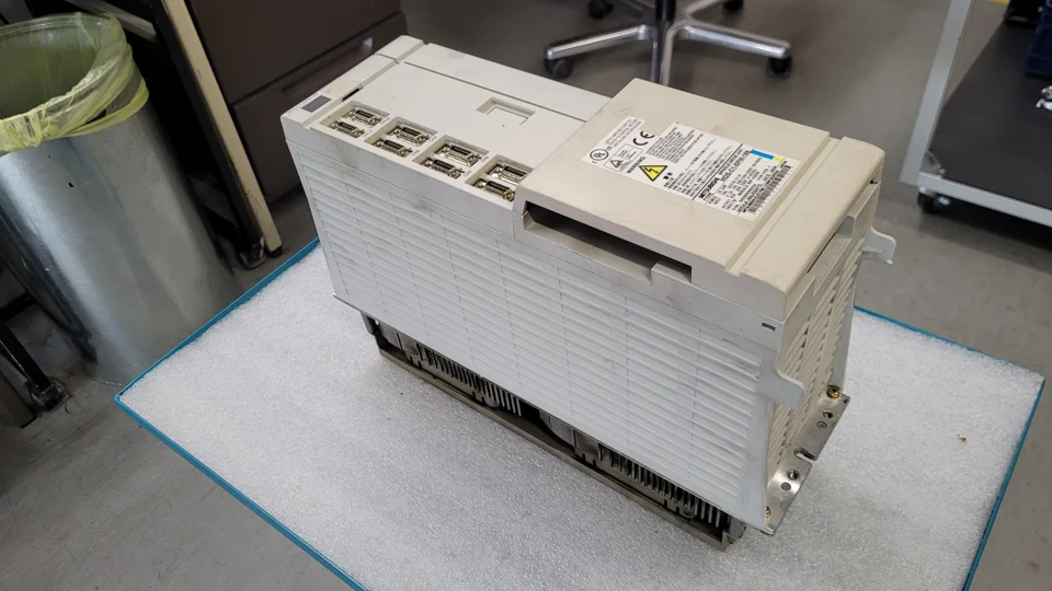 Before repair: first view
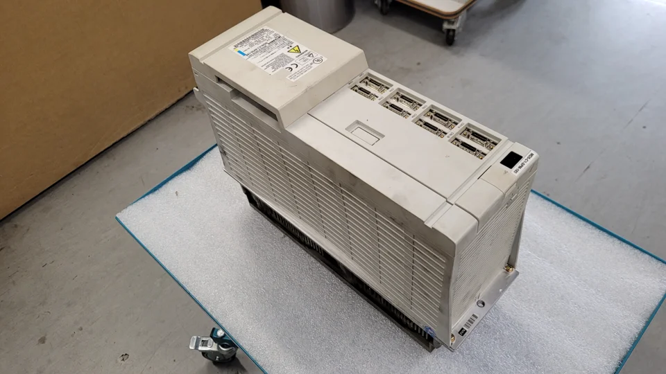 Before repair: second view
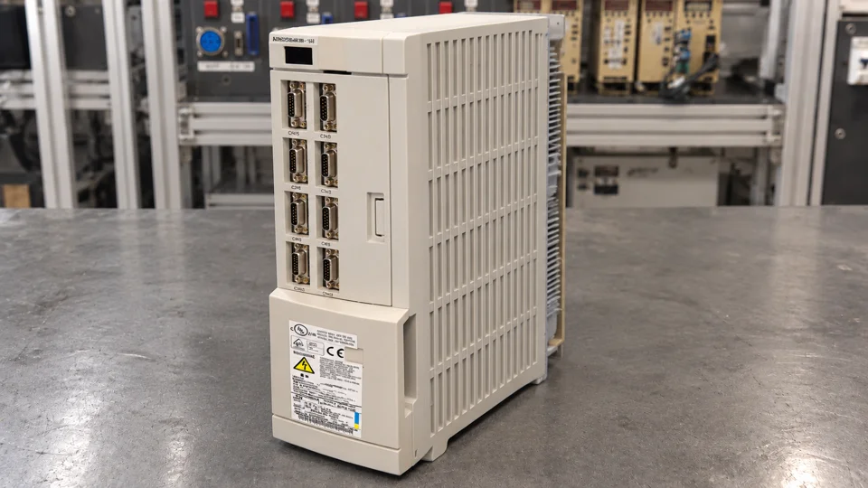 After repair: upright front view
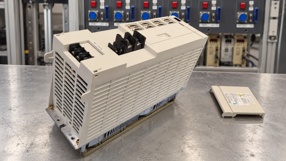 After repair: side view with removed cover
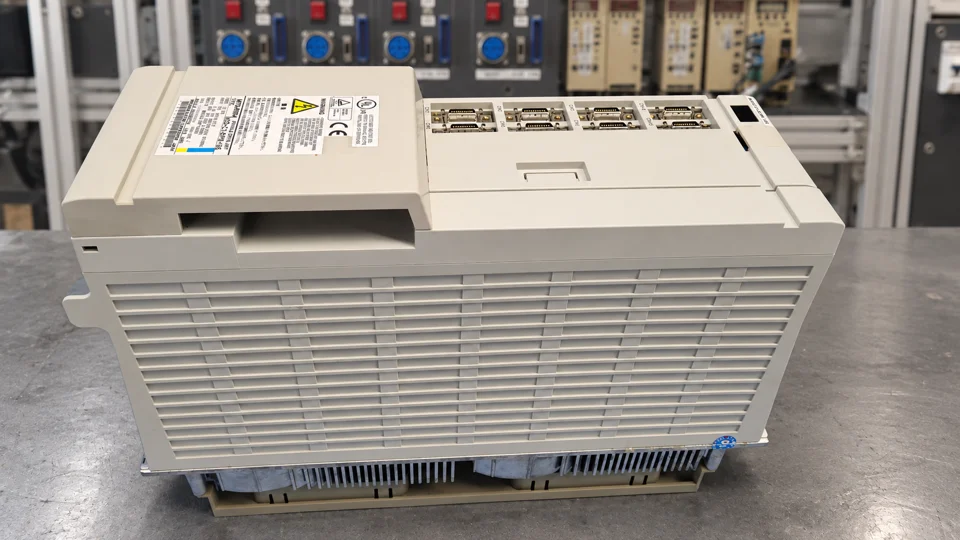 After repair: additional view
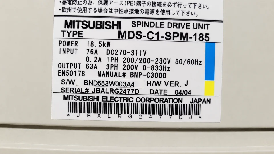 MDS-C1-SPM-185 nameplate
Repair enquiry
Please provide the full model, nameplate photo and the circumstances of the alarm. Mitsubishi MDS-C1-SPM-185 repair service · Mitsubishi drive service