09.09.2026 by Viktor Siebert
Repair of a Mitsubishi MDS-C1-SPH-150 Spindle Drive Unit with Cyclic Switching On and Off
The Mitsubishi MDS-C1-SPH-150 Spindle Drive Unit arrived at our workshop with an unusual fault pattern. The unit could be switched on, but it shut down again after only a few seconds. Shortly afterward, it attempted to start again.
This process repeated continuously at intervals of only a few seconds.
At first glance, this behavior indicated an unstable or defective internal power supply. However, the technical investigation showed that the power supply was only reacting to an excessive internal load. The actual cause of the fault was located in the power output stage.
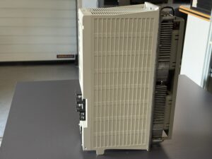
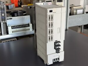
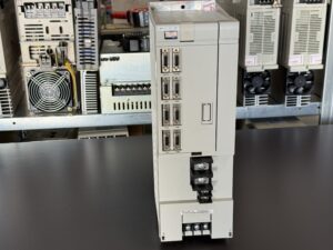
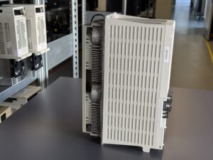
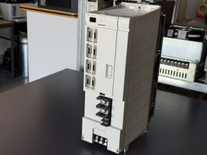
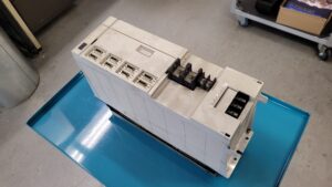
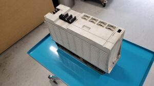
The Mitsubishi MDS-C1-SPH-150 Spindle Drive Unit
The Mitsubishi MDS-C1-SPH-150 is a Spindle Drive Unit from the MDS-C1 series. Within a CNC machine tool, it is responsible for the controlled power supply and operation of the spindle motor.
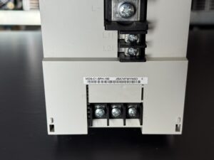
According to the nameplate, the submitted unit has a rated output of 15 kW. The power input is designed for a DC voltage of 270 to 311 V at 58 A. The output supplies up to 49 A at three phase 200 V and an output frequency from 0 to 833 Hz.
The unit also requires a separate single phase supply of 200 to 230 V for the control system, monitoring circuits and internal electronics.
The Spindle Drive Unit must perform several tasks simultaneously. It controls the speed and torque of the spindle motor, processes feedback signals, monitors motor current and DC link voltage, and protects the connected components against impermissible operating conditions.
Fault Pattern During Startup
After the unit was switched on, the internal electronics initially began their normal startup sequence. After only a short period, however, the supply voltage collapsed and the unit switched off again.
Once the internal voltage had recovered, the drive attempted to start again. A few seconds later, the same process was repeated.
This created a regular cycle:
The unit switched on.
The internal supply was placed under load.
The voltage collapsed.
The electronics switched off.
The supply voltage recovered.
The next startup attempt began.
This type of behavior is often prematurely interpreted as a power supply fault. In this case, however, the power supply was not the actual cause. It was reacting to an impermissible load created by another assembly.
Why a Power Supply Can Collapse Under Internal Load
The internal power supply provides the required auxiliary voltages for the control board, driver circuits, monitoring electronics and parts of the power stage control system.
A power supply may deliver apparently correct voltages when operating without a load. However, if a connected assembly is defective and draws excessive current, the supply voltage can collapse.
Many switched mode power supplies have internal protective functions. If the permissible load is exceeded, the power supply shuts down. As soon as the load temporarily disappears and the voltage builds up again, the power supply attempts to restart.
This process can repeat at short intervals and create the observed cyclic switching on and off.
For this reason, it is not sufficient to inspect or replace only the power supply when this type of fault occurs. It must first be determined which connected assembly is placing the excessive load on the supply.
Systematic Localization of the Fault
After opening the Mitsubishi MDS-C1-SPH-150, the unit was first cleaned and subjected to a comprehensive visual inspection.
With spindle drives of this age, we pay particular attention to:
Discoloration caused by elevated temperatures
Damaged or aged solder joints
Contaminated heatsinks and cooling channels
Slow running or blocked fans
Abnormalities in the power semiconductors
Damaged insulation areas
Thermally stressed connectors
Aged capacitors
Abnormalities in the driver stages
The internal supply voltages were then monitored during the startup process. The decisive factor was not only the level of each voltage, but also its development over time during the startup attempt.
This revealed that the supply voltage collapsed under the connected internal load.
To locate the cause, the power supply, control system, driver circuits and power output stage had to be examined separately. This procedure made it possible to determine which assembly was responsible for the excessive current consumption.
Internal Fault in the Power Output Stage
Further investigation revealed an internal fault within the power output stage.
The power output stage is responsible for converting the available DC link voltage into a controlled three phase output voltage for the spindle motor. Powerful semiconductors are used for this purpose. They process high currents while switching at a high frequency.
In the event of an internal defect, the output stage can draw excessive current or place an impermissible load on individual internal supply circuits. This can cause the auxiliary voltages of the power supply to collapse even though the power supply itself is fundamentally functional.
The cyclic switching on and off was therefore not the actual cause of the fault. It was the visible result of a protective reaction by the internal power supply.
This distinction was crucial for the repair. Repairing or replacing only the power supply would not have eliminated the fault permanently. The defective output stage would also have overloaded a repaired or replacement power supply.
Testing the Power Output Stage
The power semiconductors were checked for abnormal semiconductor paths, short circuits, leakage current and inconsistent measurements within the individual power paths.
The associated driver circuits also had to be inspected. A power semiconductor can itself be defective. However, it can also be switched incorrectly because of a defective driver supply or an impermissible control signal.
For this reason, the inspection was not limited to the power components. The following areas were also examined:
Driver stage supply voltages
Control of the power semiconductors
Galvanically isolated signal transmission
Current sensing circuits
Protection and shutdown signals
Internal auxiliary voltages
Connections between the control board and power section
Only after this complete inspection was it possible to rule out the possibility that a fault in the control circuitry could damage the repaired power output stage again.
Repair of the Mitsubishi Spindle Unit
After the fault had been clearly localized, the defective area in the power output stage was repaired.
The affected circuit sections were not considered in isolation. The associated driver areas, internal power supplies and protective circuits were also inspected.
The components that must be replaced during this type of repair always depend on the actual measurement results. Replacing individual components without first performing a detailed diagnosis would not be technically appropriate for a Spindle Drive Unit of this power class.
After the repair, the first controlled startup was performed. During this process, we checked whether the internal supply voltages remained stable and whether the unit completed the entire startup sequence without shutting down again.
The original cyclic switching on and off no longer occurred.
Testing After the Repair
A successful startup alone is not sufficient as a final test for a Mitsubishi MDS-C1-SPH-150.
A Spindle Drive Unit must also operate reliably during extended operation, changing commands and thermal load. Faults in power semiconductors, driver circuits or power supplies can be temperature dependent and may only appear after a certain operating time.
For this reason, the unit was tested over an extended period after the repair.
The following points were checked in particular:
Stability of the internal auxiliary voltages
Behavior during the startup process
Function of the power output stage
Plausibility of the current sensing circuits
Temperature development of the power assemblies
Function of the cooling system
Communication and operational readiness
Behavior during extended operation
Possible recurrence of protective shutdowns
The Spindle Drive Unit remained stable throughout the test. The cyclic switching on and off did not recur.
Why the Power Supply Was Not the Actual Cause
This repair case demonstrates a typical diagnostic trap in industrial power electronics.
The component at which a fault becomes visible is not necessarily the component that caused it.
In the Mitsubishi MDS-C1-SPH-150, the internal power supply collapsed repeatedly. At first, this could be interpreted as a classic power supply fault. However, the power supply was actually being overloaded by a defect in the power output stage.
If only the power supply had been repaired or replaced, the defective output stage would have remained in the unit. The power supply could therefore have failed again. There would also have been a risk of additional damage inside the drive.
A sustainable repair therefore requires a clear distinction between the actual cause of the fault and the resulting protective reaction.
Checking the Drive System Before Reinstallation
Before reinstalling a repaired Spindle Drive Unit, the surrounding machine system should also be inspected.
The following components and conditions should be checked:
Spindle motor
Motor cable
DC link connections
Protective conductor
Supply voltage
Control cabinet cooling
Fans and filter mats
Connectors
Feedback and sensor signals
A defective spindle motor, an insulation fault in the motor cable or a defective DC link connection can overload a repaired unit again.
The repaired Spindle Unit should therefore not be considered as an isolated component. It must always be evaluated as part of the complete drive system.
Advantages of Repairing the Original Unit
Repairing the existing Mitsubishi MDS-C1-SPH-150 makes it possible to retain the original machine configuration.
Replacing the unit with another generation may require modifications to the parameters, control system, wiring, feedback system or spindle motor. Especially with older CNC machine tools, a fully compatible replacement solution may not be available at short notice.
Repairing the original unit can therefore provide several advantages:
Retention of the existing system configuration
No extensive machine modifications
Reduced machine downtime
Lower risk during recommissioning
Continued use of existing components
Reduced consumption of resources
Conclusion
In the Mitsubishi MDS-C1-SPH-150, the cyclic switching on and off was not caused by an isolated power supply defect.
An internal fault in the power output stage loaded the power supply so heavily that the supply voltage repeatedly collapsed. After a brief recovery, the next startup attempt began and the unit switched on again.
Only the combined inspection of the power supply, driver stages and power electronics made it possible to identify the actual cause of the fault.
After the power output stage had been repaired and the subsequent functional tests had been completed, the Mitsubishi Spindle Drive Unit operated stably again. The original switching on and off at intervals of only a few seconds no longer occurred.
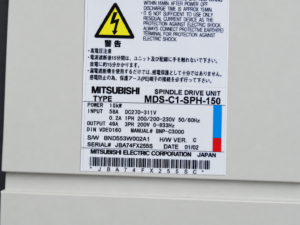
To mentioned Mitsubishi Drive: Mitsubishi MDS-C1-SPH-150 Spindle Drive Unit
More details about our Mitsubishi repair services can be found here:
Mitsubishi drive Repair by Industrypart
📞 Feel free to contact us with any questions about your Mitsubishi drive technology.
Our expert team is happy to help!
Technical Specifications
| Feature | Technical specification |
|---|
| Manufacturer | Mitsubishi Electric Corporation |
| Device type | Spindle Drive Unit |
| Model | MDS-C1-SPH-150 |
| Rated output | 15 kW |
| Power input current | 58 A |
| DC link voltage | DC 270 to 311 V |
| Control input current | 0.2 A |
| Control supply voltage | Single phase 200 to 230 V |
| Supply frequency | 50 or 60 Hz |
| Output current | 49 A |
| Output voltage | Three phase 200 V |
| Output frequency | 0 to 833 Hz |
| Hardware version | C |
| Software identification | BND553W002A1 |
| Serial number | JBA74FX255S |
| Production date | 01/02 |
| Standard reference | DIN VDE0160 |
| Manual reference | BNP-C3000 |
| Country of manufacture | Mitsubishi Electric Corporation, Japan |
Device Designations and Alternative Spellings
Mitsubishi MDS-C1-SPH-150
MDS-C1-SPH-150 Spindle Drive Unit
MDSC1SPH150
MDS C1 SPH 150
Mitsubishi 15 kW Spindle Drive
Mitsubishi MDS-C1 Spindle Controller
Fault Description
| Area | Finding |
|---|
| Customer reported symptom | Unit switched on and off repeatedly at intervals of only a few seconds |
| Visible behavior | Repeated startup followed by shutdown |
| Initial possible assumption | Unstable internal power supply |
| Actual cause | Internal fault in the power output stage |
| Technical consequence | Power output stage overloaded the internal power supply |
| Unit response | Supply voltage collapsed and the unit subsequently attempted to restart |
| Repair area | Power output stage and associated driver and supply circuits |
| Result | Stable startup with no further cyclic shutdown |
Functional Description
The Mitsubishi MDS-C1-SPH-150 supplies and controls the spindle motor of a CNC machine tool. The Spindle Drive Unit converts the DC link voltage into a controlled three phase output voltage.
The output frequency and output current are regulated according to the commanded spindle speed and load.
Its primary functions include:
Control of the spindle speed
Control of the motor torque
Control of the power output stage
Processing of motor and spindle feedback
Monitoring of the motor current
Monitoring of the DC link voltage
Monitoring of the power semiconductors
Thermal monitoring
Communication with the CNC control
Protective shutdown during impermissible operating conditions
Main Components
| Assembly | Function | Inspection information |
|---|
| Power output stage | Generates the controlled three phase motor current | Check power semiconductors for short circuits, leakage current and thermal damage |
| Gate drivers | Control the power semiconductors | Check supply voltages, pulse shape and shutdown behavior |
| Internal power supply | Supplies the control and driver circuits | Check output voltages both without load and under load |
| DC link | Provides the main power voltage | Check voltage, connections and capacitors |
| Control board | Regulation, communication and monitoring | Check power supplies, signal paths and communication |
| Current sensing circuit | Measures motor and module currents | Check offset, plausibility and signal quality |
| Heatsink | Dissipates heat generated by the power components | Check for contamination and signs of thermal stress |
| Fan assembly | Cools the power electronics | Check speed, bearing condition and airflow |
| Connection assemblies | Connect the motor, supply and control system | Check contacts, locking mechanisms and heat damage |
Alarm Messages and Troubleshooting
The following alarm messages are taken from the supplied documentation for the Mitsubishi MDS-C1 series. No definite alarm code was reported for the specific unit covered by this repair case. The table therefore serves as a general technical reference.
| Alarm | Description | Possible cause | Inspection approach |
|---|
| 30 | Over-regeneration | Excessive regenerated energy or a fault in the regeneration path | Check the regeneration circuit and operating profile |
| 31 | Overspeed | Impermissibly high motor speed | Check feedback, parameters and mechanical operation |
| 32 | Overcurrent, IPM Error | Overcurrent or protective shutdown of the power module | Check motor, motor cable, power output stage and driver circuits |
| 33 | Overvoltage | DC link voltage is too high | Check the supply and regeneration circuit |
| 34 | NC Communication CRC Error | Corrupted data transmission | Check communication cable and connectors |
| 35 | NC Communication Data Error | Invalid or disrupted communication data | Check wiring, shielding and system configuration |
| 36 | NC Communication Error | Communication between the NC and drive has been interrupted | Check the power supply and communication assemblies |
| 37 | Initial Parameter Error | Invalid or impermissible parameter setting | Compare the parameter set with the machine data |
| 3A | Overcurrent | Impermissibly high output current | Check motor, motor cable, current sensing and power section |
| 3B | Overheat, IPM Error | Power section is thermally overloaded | Check fans, heatsink, airflow and operating load |
| 46 | Motor Overheat | Impermissibly high motor temperature | Check motor cooling, load, sensor and wiring |
| 60 | Instantaneous Power Failure | Brief interruption of the supply | Check incoming supply, contacts and mains quality |
| 61 | Power Module Overcurrent | Overcurrent in the power module of the supply unit | Check the DC link and connected units |
| 6F | AD Error, PS Error | Internal measurement or power supply fault | Check auxiliary voltages and internal measuring circuits |
Recommissioning Information
Before installing the repaired unit, the following points should be checked:
Test the spindle motor for winding and insulation faults
Check the motor cable for short circuits and ground faults
Inspect the DC link connections
Check all connectors for correct and secure seating
Inspect the protective conductor connection
Check control cabinet fans and filter mats
Measure the supply voltage
Back up and compare the machine parameters
Check the feedback and sensor signals
The Mitsubishi MDS-C1-SPH-150 may only be installed and tested by qualified personnel. After the power supply has been disconnected, the discharge time of approximately 15 minutes stated on the unit must be observed.