19.09.2025 by Viktor Siebert
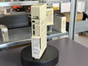
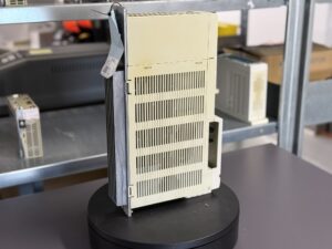
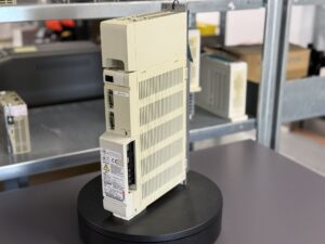
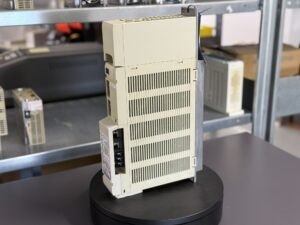
Repair Case: Mitsubishi MDS-C1-CV-37 Power Supply Unit with Alarm 6F AD Converter Error
The Mitsubishi MDS-C1-CV-37 Power Supply Unit that arrived at our workshop carried a story of frustration, lost production time, and the risks of taking the seemingly “cheaper” path in industrial maintenance. The customer had initially sent the unit to a foreign low-cost repair provider. The offer sounded tempting: a fraction of the price compared to OEM repair and a promised turnaround time of just 10 days. For a production environment under pressure, this appeared to be the perfect solution.
Reality turned out very differently. Instead of ten days, the PSU was returned after more than four weeks. Worse still, once reinstalled in the customer’s CNC machine, it did not function as expected. Instead of stable operation, the unit triggered sporadic alarms, the most critical being Alarm 6F means AD Converter Error. This particular error is serious because the A/D converter is essential for precise monitoring of internal voltages and currents. When it fails, the PSU cannot guarantee stable regulation of the DC bus. As a result, servo and spindle drives are no longer supplied consistently, leading to machine stoppages, unpredictable faults, and in the worst case, possible damage to connected modules and motors.
The customer’s production was interrupted multiple times. At first, the problem only appeared in cold conditions when the machine was powered up in the morning. But as days passed, the errors occurred more frequently, bringing production reliability into question. Operators began to lose confidence in the machine, and management realized that what was intended as a quick, low-cost fix was in fact becoming a costly liability. At this point, the customer decided to send the unit to us for a full professional repair.
When we opened the PSU, we were confronted with a shocking sight. The so-called “repair” had not only failed to address the root cause but had severely compromised the device. All of the main electrolytic capacitors had been replaced with used components of mixed brands and specifications. Some of them already showed signs of wear, bulging tops, and high ESR values. Instead of restoring reliability, the previous repair had introduced a new ticking time bomb into the system.
Even more concerning were the condition of the PCB and the control circuitry. The main control board (BN638A309G51) showed crude soldering work. Several ICs had been unsoldered and reattached with poor technique, leaving damaged pads and broken traces. In the A/D converter section, critical signal lines were bridged with improvised wiring. It was a miracle that the board powered up at all. Our analysis confirmed that the recurring 6F AD Converter Error was directly linked to these botched modifications.
We knew that a superficial fix would not be acceptable. The only way forward was a full restoration to OEM-level standards.
Repair process in detail:
- Disassembly and cleaning The unit was fully dismantled. Flux residues, dust, and contamination were carefully removed to ensure a clean inspection base.
- PCB inspection under microscope Every trace on the control board was checked. Damaged pads and cut tracks were mapped and documented.
- Restoration of control board Since the A/D section was compromised beyond reliable repair, we replaced the entire BN638A309G51 control board. The defective board was retained for documentation and analysis.
- Replacement of power components The power module 6MBP50RA060-07, part of the Intelligent Power Module (IPM), was replaced. The previous repair had not touched this critical element, even though stress traces were visible.
- Capacitor replacement All electrolytic capacitors were replaced with new, high-quality industrial-grade parts. Unlike the used and mismatched ones previously installed, these were matched to the original specifications, ensuring long-term stability.
- Trace reconstruction Several areas of the power stage PCB had been damaged. Using precision wire bridges and reflow techniques, we reconstructed critical traces, restoring the PCB integrity.
- Functional tests The unit was reassembled and connected to our dedicated test stand. First, insulation and continuity tests were carried out. Then, the DC bus was energized, and we verified voltage stability under different loads.
- Thermal stress testing To simulate real-world conditions, the PSU was operated under load for several hours, including repeated cold starts to reproduce the customer’s original problem. No further 6F errors occurred.
- Integration test Finally, the PSU was paired with servo and spindle modules, simulating a full CNC system. Communication with the NC was verified, and fault logs were checked. The unit passed all tests without issues.
The repair process took significantly more effort than a standard overhaul, primarily because of the prior unprofessional intervention. But the result justified the work: the PSU was restored to reliable condition, with stability and safety at the level expected from Mitsubishi systems.
Customer benefit:
Once reinstalled in the machine, the PSU ran flawlessly. The sporadic stoppages disappeared, and the production line regained its reliability. For the customer, the biggest gain was not only avoiding the purchase of a costly new unit but also restoring confidence in the machine. The operators could once again rely on their CNC equipment without the fear of sudden failures.
Lessons learned:
This case highlights the risks of entrusting complex electronics to low-cost providers without proven expertise. While the initial price seemed attractive, the hidden costs of downtime, repeated errors, and loss of trust were far greater. In contrast, a professional repair with preventive replacement of critical components ensures longevity, reduces risks, and supports sustainability.
The story of this MDS-C1-CV-37 PSU is a reminder that in industrial environments, quality is not optional, it is the foundation of reliable production.
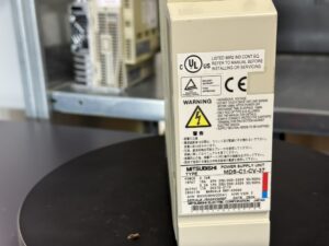
To mentioned Mitsubishi Drive: Mitsubishi MDS-C1-CV-37 Power Supply Unit
More details about our Mitsubishi repair services can be found here:
Mitsubishi drive Repair by Industrypart
📞 Feel free to contact us with any questions about your Mitsubishi drive technology.
Our expert team is happy to help!
Technical Summary of the Unit
| Feature | Value |
|---|
| Manufacturer | Mitsubishi Electric Corporation (Japan) |
| Type | MDS-C1-CV-37 |
| Power | 3.7 kW |
| Input Voltage | 3-phase 200–230 V AC, 50/60 Hz |
| Input Current | 16 A |
| Control Power | 1-phase 200–230 V, approx. 0.2 A |
| Output Voltage | DC 270–311 V |
| Output Current | 17 A |
| Cooling | Natural convection, optional fan depending on cabinet design |
| Weight | approx. 6–8 kg |
| Dimensions | W ~60 mm, H ~300 mm, D ~200 mm |
| Control | For MELDAS CNC systems, compatible with MDS-C1 servo and spindle amps |
| Manual | BNP-C3000 |
Application Environment & Compatible Devices
- Typical Machines: CNC tools such as lathes and milling machines from Mazak, Mitsubishi, DMG Mori, etc.
- Controls: Compatible with Mitsubishi MELDAS-C1 controls.
- Compatible Modules: Supplies MDS-C1 servo and spindle amplifiers.
- Conditions:
- Temperature: 0–55 °C
- Humidity: < 90 % (non-condensing)
- Install in protected cabinet, free of oil mist and dust
Functional Description
The MDS-C1-CV-37 supplies servo and spindle amplifiers with stable DC bus voltage.
- Functions:
- Rectifying and smoothing mains input
- Overvoltage, undervoltage, overcurrent, and overheat protection
- Internal NC communication
- Status via LED indicators
Alarms & Troubleshooting
Extract from official alarm list
| Code | Error Description | Meaning | Remedy |
|---|
| 61 | Power module error | Overcurrent in IPM detected | Check/replace module |
| 63 | Compensation regen err. | Regen transistor ON too long | Check mains/load conditions |
| 65 | Rush relay error | Pre-charge relay did not switch | Check relay/circuit |
| 67 | Open phase | One input phase missing | Check supply |
| 68 | Watch dog | Software process timeout | Inspect control/board |
| 69 | Ground fault | Ground fault in motor or cabling | Check motor/cables |
| 6A | Contactor met | External contactor ON during READY OFF | Verify wiring |
| 6B | Rush relay met | Pre-charge relay still ON | Inspect relay |
| 6C | Main circuit error | Main capacitor charging abnormal | Replace capacitors |
| 6D | Memory error | Error in power supply memory | Inspect/replace board |
| 6F | AD Converter error | AD converter error detected | Check/replace control board |
| 71 | Emergency stop | Contact opened even during READY ON | Verify wiring |
| 75 | Overvoltage | DC bus > 410 V | Check input voltage |
| 77 | Module overheat | Overheating in IPM | Check cooling |
Components
| Component | Designation |
|---|
| Control Board | BN638A309G51 / RK415D |
| Power Module | 6MBP50RA060-07 (IPM) |
| Power Stage | BN638A104G51 / RK481 |
| Cooling | Heat sink, optional fan |
| Power Supply Module | Integrated, DC bus 270–311 V |
| Connectors | Power input, DC bus, control, communication |