21.01.2026 by Viktor Siebert
Repair of a Mitsubishi MDS-B-SVJ2-10 Servo Drive Unit with Alarm 10 (Undervoltage)
Initial Situation and Fault Description.
The Mitsubishi Servo Drive Unit MDS-B-SVJ2-10 was sent to us with the reported Alarm 10 – Insufficient Voltage (Undervoltage). According to the customer, the fault initially occurred sporadically. In some cases, the axis could be released again after a reset, while in other cases the alarm appeared already at power-up or immediately when READY-ON was activated.
Alarm 10 indicates that the DC bus voltage in the main circuit has dropped below the permissible limit. An important detail is that this alarm is only monitored in the READY-ON state. This makes it particularly critical, as many external causes must first be excluded before the drive unit itself can be identified as the source of the problem.
Initial Inspection and Fault Isolation
As with all MDS-B units, the first step was a structured incoming inspection:
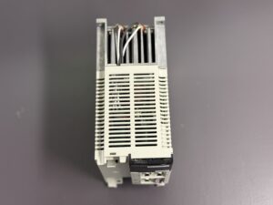
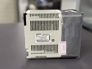
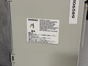
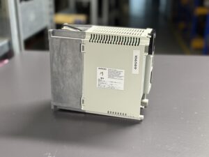
• Visual inspection of the housing
• Inspection of ventilation openings and cooling channels
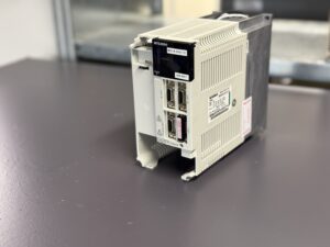
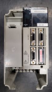
• Verification of connectors and terminals
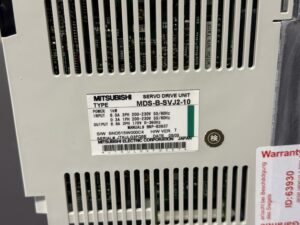
• Cross-check of nameplate data
Externally, no obvious damage was visible. The cooling fan was running, there were no burnt components and no mechanical defects. This is typical for Alarm 10, as the fault is electrical in nature and not visually apparent.
Electrical Diagnosis According to Checklist
In the next step, the drive was not opened immediately, but instead subjected to systematic measurements, following the same logic that would be applied during on-site diagnostics at the customer’s facility:
• Measurement of the input voltage on L1–L2–L3
• Verification of phase balance
• Inspection of the external contactor
• Simulation of stable supply conditions
All external parameters were within specification. This clearly indicated that the root cause was located inside the drive unit.
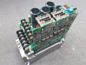
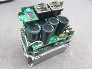
After opening the unit, a typical picture of aging power electronics became evident. The DC bus capacitors showed increased ESR values, even though they appeared visually intact. This is exactly where the risk lies: under load or during READY-ON, such capacitors can momentarily collapse, triggering Alarm 10.
Repair and Preventive Measures
The repair was not limited to a single component but carried out according to an internal preventive maintenance checklist:
• Replacement of the affected DC bus capacitors
• Inspection of the charging and pre-charge resistors
• Verification of the contactor control circuit
• Inspection of the voltage monitoring circuitry
• Cleaning of the power board
• Inspection of solder joints in high-current areas
• Replacement of all critical components according to standard
This preventive approach is essential, because in cases of undervoltage faults, several components often age simultaneously. A simple component replacement without a comprehensive inspection often leads to follow-up failures.
The Key Aspect: Testability
After repair, the MDS-B-SVJ2-10 was tested on our dedicated Mitsubishi test bench.
The test procedure included:
• Stable READY-ON cycling
• Repeated power ON and OFF sequences
• Simulation of load changes
• Continuous operation under thermal stress
• Monitoring of the DC bus voltage
• Verification of alarm triggering behavior
Especially for Alarm 10, this testing step is critical. A drive can appear fault-free under no-load conditions and still fail under real operating conditions. Only a reproducible load test provides reliable assurance.
The drive remained fully stable over multiple cycles, with no recurrence of the undervoltage alarm.
Practical Conclusion
Alarm 10 is not a trivial power supply issue. In many cases, it is an early warning signal of aging power electronics. Simply checking the supply or repeatedly resetting the drive increases the risk of unexpected machine downtime.
Through preventive repair based on a structured checklist and proper testing under realistic conditions, the service life of these drives can be significantly extended.
To mentioned Mitsubishi Drive: Mitsubishi Servo Drive Unit MDS-B-V1-35
More details about our Mitsubishi repair services can be found here:
Mitsubishi drive Repair by Industrypart
📞 Feel free to contact us with any questions about your Mitsubishi drive technology.
Our expert team is happy to help!
Mitsubishi MDS-B-SVJ2-10
Technical Specifications
| Parameter | Value |
|---|
| Device Type | AC Servo Drive Unit |
| Series | Mitsubishi MDS-B |
| Model | MDS-B-SVJ2-10 |
| Rated Power | approx. 1 kW |
| Input Voltage | 3-phase 200–230 V AC |
| Input Current | approx. 8 A |
| Output Voltage | approx. 170 V AC |
| Output Current | approx. 8.8 A |
| Cooling | Forced air cooling |
| Construction | Modular design |
| Manufacturer | Mitsubishi Electric |
| Manual | BNP-B3937 |
Typical Applications
• CNC machining centers
• Lathes
• Machine tools with feed axes
• Systems with frequent start-stop operation
Functional Description
The MDS-B-SVJ2-10 supplies AC servo motors with regulated voltage and current. Internal monitoring continuously measures the DC bus voltage. If this voltage drops below the defined threshold, Alarm 10 is triggered to prevent unstable control behavior.
Alarm Messages (Excerpt)
| Alarm Code | Description | Cause | Action |
|---|
| 10 | Undervoltage | DC bus voltage drop | Check supply and drive |
| 30 | Over-regeneration | Resistor overloaded | Check regeneration |
| 32 | Overcurrent | Power stage fault | Inspect power electronics |
| 33 | Overvoltage | DC bus too high | Check braking circuit |
| 45 | Fan stop | Cooling failure | Replace fan |
Components
| Assembly | Designation | Function |
|---|
| Control board | J2B-C13C | Control and monitoring |
| Power board | RK822B-6 | Power conversion |
| Capacitor board | RK823Z | DC bus |
| Power stage | SVJ2-10 | Output stage |
Final Recommendation
For MDS-B servo drives, Alarm 10 should always be interpreted as a technical warning signal. Preventive refurbishment including proper testing helps avoid unplanned downtime and extends the operational lifetime of the drive.