03.08.2025 by Viktor Siebert
Mitsubishi MDS-B-SVJ2-07 Servo‑Drive with Alarm AL 32
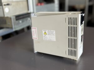
Arrival of the servo drive and customer inquiry.
Recently a Mitsubishi MDS-B-SVJ2-07 servo drive with error message AL 32 arrived at our workshop. The unit had abruptly brought the customer’s machine to a standstill. The operator had already tried to remedy the fault by changing cables and motor, but the overcurrent alarm persisted. After a brief phone call, during which we recommended the usual immediate measures such as checking the connections and running a no‑load test, he decided to send the unit in for repair.
When a device arrives, we create a work order and it goes straight to the workshop. On the same day our workshop manager assesses the scope of the repair and prepares the analysis. This structured procedure shortens the processing time and lays the foundation for a successful repair.
Fault analysis and initial diagnosis
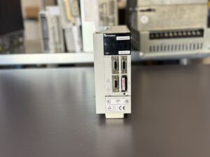
The initial visual inspection revealed no external damage, but a strong smell of burnt plastic indicated that the electronics had been overloaded. When connected to our test bench the AL 32 alarm reappeared immediately. This error points to overcurrent in the power section and can be triggered by short circuits, defective power transistors or aged capacitors. Since the customer had already ruled out external influences such as motor and cables, we focused on the interior.
After opening the unit we discovered burst electrolytic capacitors, a damaged gate‑driver module and burnt‑through transistors. Discoloured resistors and heat marks on the circuit board confirmed that internal components had failed. These findings guided the subsequent repair steps.
Repair and replacement of components
Our repair strategy is preventive: we not only rectify the specific defect, but also replace components that are known to wear out. After dismantling the drive we desoldered the defective transistors and installed new, powerful modules. At the same time we replaced the capacitors in the intermediate circuit as well as the gate‑driver and renewed aged resistors.
The replacement was accompanied by thorough cleaning. Heat sinks, fans and circuit boards were freed from dust and oil, old thermal compound was renewed and worn fans were replaced with quiet models. Fuses were replaced, solder joints tightened and ageing opto‑couplers exchanged to avoid measurement errors and cold joints.
Preventive measures and quality assurance
Prevention plays a central role for us. In addition to replacing obviously defective parts we systematically replace components that frequently fail in order to extend the service life of the drive. Thanks to our large stock of spare parts we can provide the necessary components quickly, so most repairs are completed within a few days. Throughout the process we keep our customers informed and obtain their approval if additional work becomes necessary.
Final tests and result
After the repair the drive undergoes intensive functional testing. We connect the unit to an original Mitsubishi servo motor and test it on a bench that simulates real machine conditions. The test includes varying loads, acceleration and braking processes as well as several hours of continuous operation. During this phase we monitor current draw, temperature and the stability of the control signals.
Our test benches are largely automated and allow uniform and reproducible testing. Only after the device has passed all tests without errors is it released for dispatch. Finally we clean the drive again, pack it carefully and include a test report. We provide a guarantee on every repair because we are convinced of the quality of our work.
The Mitsubishi MDS-B-SVJ2-07 now operates reliably again in the customer’s production line. The AL 32 overcurrent error no longer occurs and the plant runs without unexpected downtime. Thanks to the preventive approach and careful tests we were able to eliminate the causes sustainably and extend the service life of the drive.
To mentioned Mitsubishi Drive: Mitsubishi MDS-B-SVJ2-07 Servo‑Drive
More details about our Mitsubishi repair services can be found here:
Mitsubishi drive Repair by Industrypart
📞 Feel free to contact us with any questions about your Mitsubishi drive technology.
Our expert team is happy to help!
Technical Summary of the Unit
| Parameter | Value |
|---|
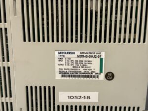
| Type | MDS-B-SVJ2-07 |
| Rated power | 0.7 kW |
| Input (power section) | 3.8 A (three‑phase) 200 to 230 V, 50/60 Hz |
| Input (control section) | 0.3 A (single‑phase) 200 to 230 V, 50/60 Hz |
| Output | 6.0 A (three‑phase) 170 V, 0 to 360 Hz |
| Manual | BNP‑B3937 |
| Software version | BND515W000C4 |
| Hardware version | Version P |
| Manufacturer | Mitsubishi Electric Corporation, Japan |
Operating environment and integration with other devices
The MDS‑B‑SVJ2‑07 is a servo amplifier for machine tools and works in a drive chain with a Mitsubishi CNC controller, a matching AC servomotor (e.g., the HC series) and a regeneration resistor. It is supplied via a three‑phase mains connection that is protected by circuit breakers and contactors. A separate control power supply ensures that position data are retained when the main power is turned off.
The following environmental conditions apply for safe operation:
- Temperature: 0 °C to +40 °C without freezing.
- Humidity: up to 80 % relative humidity for the amplifier, without condensation.
- Voltage quality: The mains supply must be stable and run through protective devices such as fuses and contactors so that it can be safely disconnected in the event of a fault.
The servo amplifier is usually used together with servomotors of the HC‑S, HC‑L and HC‑M series and an external regeneration resistor.
Function description
The unit of the MDS‑B‑SVJ2 series uses a sinusoidal PWM current control. It has an integrated dynamic braking circuit and a separate control power supply. Compared with older SVJ models, the SVJ2 series features a battery for absolute position storage, additional monitoring functions and the option of external observation. Digital inputs (e.g. emergency stop) and outputs for controlling the motor brake or a contactor as well as analogue ± 10 V outputs are also available. This equipment enables precise positioning and speed control in highly dynamic applications.
Alarm messages and troubleshooting
| Alarm code | Description / cause | Solution approach |
|---|
| AL 10 – Under‑voltage | The DC bus voltage falls below 200 V, which indicates insufficient supply power or a defective amplifier. | Check the supply power, increase it if necessary; if the problem recurs, replace the amplifier. |
| AL 13 – Software processing error | Internal error in the processor unit. | Check grounding and ambient temperature; minimise interference; replace the unit if the error persists. |
| AL 15 – Memory error | Fault in the internal memory unit. | Replace the amplifier. |
| AL 17 – A/D converter error | Incorrect analogue‑to‑digital converter value, e.g. due to an interrupted detector cable. | Check grounding and the ambient environment; check and replace connectors and detector cable as necessary. |
| AL 18 – Initial motor‑encoder communication | Communication with the motor detector cannot be established during initialisation. | Swap connections with another axis amplifier to identify the source of the fault; replace the faulty detector or amplifier. |
| AL 22 – LSI error | Error in the logic IC of the amplifier. | Check grounding and ambient temperature; if it recurs, replace the unit. |
| AL 24 – Ground fault / battery under‑voltage | Ground fault in the motor cable or voltage drop in the absolute‑position battery. | Check the motor cable and connections, insulate the defective section; check the battery voltage and replace the battery if necessary. |
| AL 25 – Absolute position lost | The absolute position signal has been lost because the detector cable was unplugged when the power was off. | Connect the detector cable and switch the unit on again after correcting the fault. |
| AL 2C – EEPROM/LED error on the motor | The LED in the motor detector is worn out or the EEPROM data are faulty. | Replace the motor detector and ensure a proper environment. |
| AL 2F – Motor‑encoder communication interrupted | Communication with the motor detector is interrupted during operation; possible causes are poor grounding or incorrect parameters. | Shield the motor cable and ground it correctly at only one point; adjust parameters; check the regeneration resistor. |
| AL 30 – Over‑regeneration | The regeneration resistor heats up due to high mains voltage or incorrectly set parameters. | Check mains voltage; adjust acceleration and deceleration parameters and current limits; use a larger regeneration resistor if necessary. |
| AL 31 – Over‑speed | The motor speed exceeds the permitted limit. | Check the mechanics and motor cable for short circuits or ground faults; replace the faulty component. |
| AL 32 – Over‑current in the power section | Over‑current in the power module due to a defective amplifier, excessively high mains voltage, defective regeneration resistor or missing bridge between the P and D terminals. | Check motor cable and connections; measure mains voltage; check the regeneration resistor and the P‑D bridge; replace the defective amplifier; adjust parameters. |
| AL 33 – Over‑voltage | The DC bus voltage exceeds the permitted value. |
Use an optional regeneration resistor; check mains voltage. |
Components of the device
| Component | Label on the board / Description | Quantity |
|---|
| Power board with control board | The board is marked “J2B‑P21 3” or “BC386A208G53A E3”. This board contains the power electronics and control logic. | 1 piece |
| Power unit | Denotes the power pack (IGBT modules), the heat sink and the power supplies. | 1 piece |
Note on operation
Practical experience shows that typical fault symptoms of Mitsubishi servo modules are jerky motor operation, failure of the device to power up or overload messages. Immediate measures include testing with another motor, checking cable connections and running a test without load. If these measures do not help, the fault is often found in the power section of the drive module.