02.10.2026 by Viktor Siebert
Mitsubishi MDS-B-SPJ2X-37 with Alarm 32 and Alarm 10
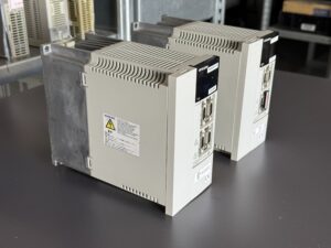
Two Mitsubishi Spindle Drive Units of type MDS-B-SPJ2X-37 arrived at industrypart with different fault reports: one unit was delivered with Alarm 32, the second with Alarm 10. Examination nevertheless revealed a common finding. Both spindle drives had a defective power output stage. Aged power components and capacitors were also identified. Cooling was another concern: the fan was dirty and barely rotating.
This case illustrates why a repair cannot rely on interpreting an alarm number alone. Two different monitoring functions can draw attention to damage in the same area. Conversely, an alarm does not by itself prove which individual component has failed. Electrical examination and the actual condition of the unit remain decisive.
What the two alarms mean
The supplied Mitsubishi manual excerpt identifies Alarm 32 as POWER MODULE ERROR. It describes excessive current flowing through a power component in the spindle drive. Apart from an internal defect, external factors are therefore possible, including faults in the motor cable, a motor insulation problem or excessive load. The timing of the alarm helps narrow the investigation.
Alarm 10 is called UNDERVOLTAGE in the same excerpt. Monitoring detects insufficient DC voltage in the DC bus. This bus connects the incoming supply to the power output stage. An undervoltage alarm may be associated with the supply, a contactor, phase loss or an internal problem. On its own, it does not conclusively identify defective capacitors or power transistors.
These descriptions come from the MDS-B-SPJ2 series documentation. The available documents do not explicitly assign all limits to the special SPJ2X designation. We therefore use the alarm descriptions for technical context and distinguish them from findings confirmed on the actual equipment.
The spindle drive’s function
The spindle drive controls the electrical supply to the spindle motor of a CNC machine tool. Its power electronics provide the currents required by the motor. Control and feedback ensure that the spindle responds to the commands. The power section, control system and connected motor hardware must be matched.
The output stage is subjected to electrical and thermal stress during operation. Acceleration and deceleration also produce changing loads. Heat generated inside the drive must be removed through the intended cooling surfaces and airflow. The fan is therefore a functional part of the drive, not a minor accessory.
A common finding behind different alarm reports
Our workshop confirmed a defective power output stage in both units. The different customer reports thus led to a comparable repair requirement. This individual case does not mean that every Alarm 10 or Alarm 32 is automatically caused by the same damage.
Alongside the output stage, attention focused on aged power components and capacitors. Depending on their circuit position, capacitors store energy, smooth voltages and help stabilise supplies. Their electrical characteristics can change with age. The affected components must be identified through testing, not solely by their appearance.
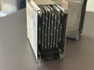
Restricted cooling was particularly noticeable. According to the workshop findings, the fan was dirty and barely turning. The intended airflow was therefore no longer reliably available. Insufficient cooling probably accelerated component ageing. However, there is no complete record of temperatures during the units’ previous machine operation. Thermal stress consequently remains a plausible contributing cause, whereas the output-stage defect is confirmed.
What matters during repair
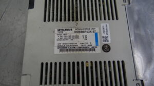
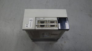
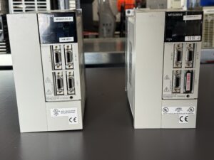
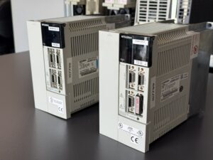
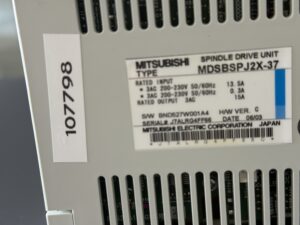
The supplied photographs document the units before and after repair. The technical focus of this case is the defective power output stage combined with aged components and restricted cooling. A complete list of all individual parts actually replaced is not included in the available documentation.
For this damage pattern, a professional investigation covers the entire affected functional area. This includes power semiconductors, their drive circuits, the power supply and associated capacitors. Connections and visible signs of thermal change also deserve attention. This explains the scope of examination; it does not replace an actual parts replacement list.
The cooling path must also be considered during repair. A repaired power section still needs adequate heat removal. Fan movement and function, air passages and cooling surfaces are therefore important inspection points. The findings determine what cleaning or replacement is needed. This article does not claim that a blanket replacement of particular components was performed.
Examination at the connected test bench
The material includes original footage of the spindle drive connected to a test bench. This adds a practical view of testing to the photographs. A test setup can be used to examine the interaction between the drive, its control and connected hardware. There is more to assess than simply switching on a display.
Meaningful functional testing includes enable behaviour, feedback, alarm status and behaviour under different operating conditions. The actual load, speed and test duration cannot reliably be established from a short video excerpt. Specific measurements, a load test lasting several hours or successful recommissioning at the customer’s machine are therefore not additionally claimed for this case.
Preventive measures for machine operators
Cooling condition should be checked regularly, with the environment taken into account. Dust and oily deposits can restrict airflow. Unusual fan noise, stiff rotation or recurring temperature-related faults should be investigated early. Control cabinet ventilation and unobstructed air inlets and outlets also matter.
When an alarm occurs, record when it appeared: at power-on, at enable, during acceleration or under machining load. Repeated resetting does not replace diagnosis. Internal work and electrical measurements must be carried out by appropriately qualified personnel, observing the unit’s discharge and safety instructions.
In these two Mitsubishi MDS-B-SPJ2X-37 units, different alarm reports led to the same confirmed finding in the power output stage. The barely turning fan also shows why cooling and component ageing should be considered together during troubleshooting.
Price, Lead Time and Further Information
Please contact us for the price and lead time of repair or a suitable replacement for the Mitsubishi Spindle Drive Unit MDS-B-SPJ2X-37.
Further information about our repair services for Mitsubishi servo and spindle drives is available here:
https://www.industrypart.com/manufacturers/mitsubishi
Please contact us with a nameplate photograph and the complete alarm display. Our team will assist with the technical assessment, repair and testing of your unit.
Technical Specifications
| Feature | Technical information |
| Manufacturer | Mitsubishi Electric Corporation, Japan |
| Equipment | Spindle Drive Unit |
| Model on photographed nameplate | MDSBSPJ2X-37 |
| Alternative designation | MDS-B-SPJ2X-37 |
| Rated input, first line | 3AC 200–230 V, 50/60 Hz, 13.5 A |
| Rated input, second line | 3AC 200–230 V, 50/60 Hz, 0.3 A |
| Rated output | 3AC, 15 A |
| Hardware revision | H/W VER. C on the photographed unit |
| Date marking | DATE 06/03, without a confirmed interpretation of the date format |
| Cooling | Heatsink and fan, supported by photograph and workshop information |
| Power rating, dimensions, weight | Not reliably established for the specific X version |
| Motor and CNC configuration | Specific types and parameters not supplied |
| Manual reference | Supplied Chapter 11 Troubleshooting excerpt; comparison with Mitsubishi BNP-B2164A(ENG), MDS-B-SPJ2 Series |
The nameplate values apply to the photographed unit. The second nameplate is not separately documented. The model suffix 37 is not used here to infer a verified power rating.
Application and Compatible Equipment
Spindle drive for CNC machine tools. Before replacement, compare the complete model designation including X, hardware and software revisions, motor assignment, feedback, connections and machine parameters. General equivalence to the MDS-B-SPJ2-37 version without X has not been established.
Functional Description
The power path connects the supply through the DC bus to the three-phase motor output. The control system processes commands and feedback. Protection functions monitor relevant electrical operating conditions. The exact communication and feedback arrangement must match the machine.
Components
Designations and quantities are taken from the supplied assembly list. They describe the documented unit structure and are not a list of replaced parts. Functions and inspection points are general technical context.
| Assembly | Designation in supplied list | Quantity | Function and general inspection point |
| Control board | RK811C or BN638A175G51 | 1 | Control and signal processing; check supplies, signals and connections |
| Capacitor board | RK823Z | 1 | Capacitor assembly; check component condition and electrical characteristics |
| Power board | RK822C-6 or BN638A248G51 | 1 | Part of the power electronics; examine power path and associated circuitry |
| Power section | Leistungsteil | 1 | Power conversion; examine semiconductor condition and thermal interface |
Alarms and Troubleshooting
The following table is a reference from the supplied MDS-B-SPJ2 manual excerpt, not confirmation of all functions and limits for the X version. Check the appropriate unit-specific documentation before applying it to a machine. Only Alarm 32 and Alarm 10 were reported for the units delivered.
| Code | Original designation | Technical meaning | Possible cause and action from the excerpt |
| 10 | UNDERVOLTAGE | Insufficient DC bus voltage | Investigate supply, phase loss, contactor and internal faults |
| 12 | MEMORY ERROR 1 | ROM checksum or RAM check error | Check repeatability, grounding and interference; replace unit if required |
| 13 | SOFTWARE PROCESS ERROR | Data processing not completed in time | Check repeatability and EMC environment; replace unit if required |
| 17 | A/D CONVERTOR ERROR | Current detection initialisation error | Investigate grounding, interference and the unit |
| 21 | NO SIGNAL DETECTION (ENC) | Orientation encoder A/B/Z signal fault | Check parameters, connectors and encoder cable |
| 24 | GROUND FAULT | Ground fault detected at Ready ON | Examine motor cable, connections and motor insulation |
| 30 | EXCESSIVE REGENERATION | Regenerative capacity limit reached | Check braking resistor, parameters and start-stop duty |
| 31 | OVERSPEED | Motor speed above monitoring limit | Check speed command, parameters and feedback |
| 32 | POWER MODULE ERROR | Excessive current in power component | Check timing, load, parameters, motor cable, insulation and supply |
| 33 | OVERVOLTAGE | Excessive DC bus voltage | Check braking resistor wiring and supply including disturbances |
| 42 | FEEDBACK ERROR (MOTOR PLG) | Motor feedback fault | Check shielding, wiring and signal waveforms |
| 46 | MOTOR OVERHEATING | Motor thermal protection operated | Investigate motor load and cooling using machine documentation |
Alarm 32 is not equivalent to a separate overtemperature alarm. The manual excerpt lists 3B for that purpose with an explicit limitation to certain power ratings; it is not presented here as a guaranteed function of this unit.
Preventive Measures
Check fan operation, air passages and heatsinks regularly. Have deposits removed professionally. Document recurring faults together with operating conditions. Include motor cables, connections and supply in diagnosis. Assess component ageing through electrical testing. Set maintenance intervals according to operating hours and environmental conditions.
Sources and Editorial Basis
Workshop information about two units, original photographs, assembly list and test footage from this case. Alarm descriptions from “Alarme und Troubleshooting-10(1).pdf”, Chapter 11. Manufacturer manual used as a series reference:
https://dl.mitsubishielectric.com/dl/fa/document/manual/cnc/bnp-b2164(eng)/bnp-b2164(eng)a.pdf
Repair details are deliberately limited to supported information. The complete parts replacement list, measurement records, exact test duration and feedback after installation are not documented.
industrypart GmbH | MDS-B-SPJ2X-37 |