28.09.2026 by Viktor Siebert
Mitsubishi MDS-B-SPJ2-75 only starts when warm: Why the machine remained switched on for months
A CNC machine is normally shut down after work in accordance with operating procedures. For this customer, however, switching it off had become a problem: his Mitsubishi MDS-B-SPJ2-75 spindle drive worked perfectly after warming up, but did not function when cold. To avoid repeated starting problems, the customer reported leaving the machine switched on for months.
Eventually, the Spindle Drive Unit arrived at industrypart. The unit was not functioning on arrival. After warming up, it operated again. This transition between failure and apparently normal operation is what makes the case interesting. A successful functional test on an already warm unit alone would not have adequately captured the original problem.
A spindle drive with a temperature-dependent fault
The MDS-B-SPJ2-75 belongs to Mitsubishi’s MDS-B-SPJ2 spindle drive series. Acting as the link between the electrical supply, CNC control and spindle motor, the drive provides the electrical power required by the motor. Control and feedback enable the commanded speed to be maintained. Depending on the machine configuration, functions such as spindle orientation are also part of the interaction between the drive and the control.
For machine operation, simply having voltage present is therefore not sufficient. The internal power supply, control electronics and enable signals must also start correctly. If this startup process is disrupted, the entire spindle function can be unavailable, even though the unit operates again after a temperature change.
No specific alarm code has been supplied for this case. The fault is therefore deliberately described as “not functioning when cold, operational after warming up”. Assigning it to Alarm 10, for example, would not be justified without a corresponding indication or measurement. The filename of an alarm list is not evidence of an alarm that actually occurred either.
Why warming up can temporarily conceal a fault
Electronic components and connections do not behave identically at every temperature. With a fault of this kind, potential areas to investigate include the internal power supply, startup circuits, aged capacitors and temperature-dependent connection problems. These are possible explanations, not a confirmed component diagnosis for this unit.
The internal power supply deserves particular attention: if the required auxiliary voltages are not stable at power-up, the control and monitoring circuits cannot start correctly. A change caused by warming may allow the unit to complete startup. Comparing the cold and warm conditions is therefore crucial when narrowing down the fault.
However, observing that “it runs when warm” does not yet identify which component needs replacing. Measurements and targeted examination are required. External factors such as the incoming supply, connectors and enable signals must also be considered during troubleshooting. Temperature-dependent behaviour is a valuable clue, but it does not replace a complete diagnosis.
Months without switching off: a workaround for the starting problem
The customer had found a way to avoid another cold start: the machine remained switched on. According to his account, this kept production running for months. The cause of the problem, however, remained present.
The practical drawback becomes apparent when a shutdown is necessary. Maintenance, an interruption to the power supply or a planned stoppage can require a new start. A drive that only starts reliably when warm makes that moment difficult to plan. Dependence on prior warming should therefore be investigated early.
This case also demonstrates the importance of the customer’s description. Knowing that the machine had not been switched off for an extended period changes the interpretation of an initially uneventful warm run. Fault recording should therefore include the history and startup conditions, as well as the current display indication.
Incoming inspection and test bench documentation
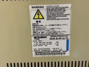
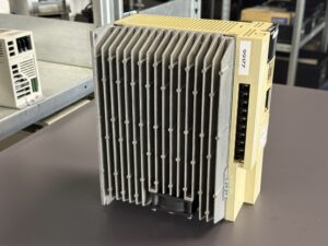
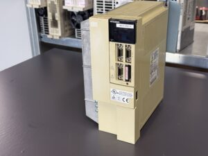
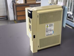
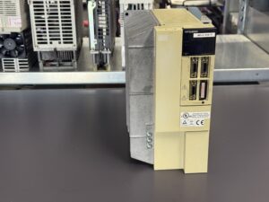
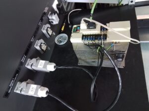
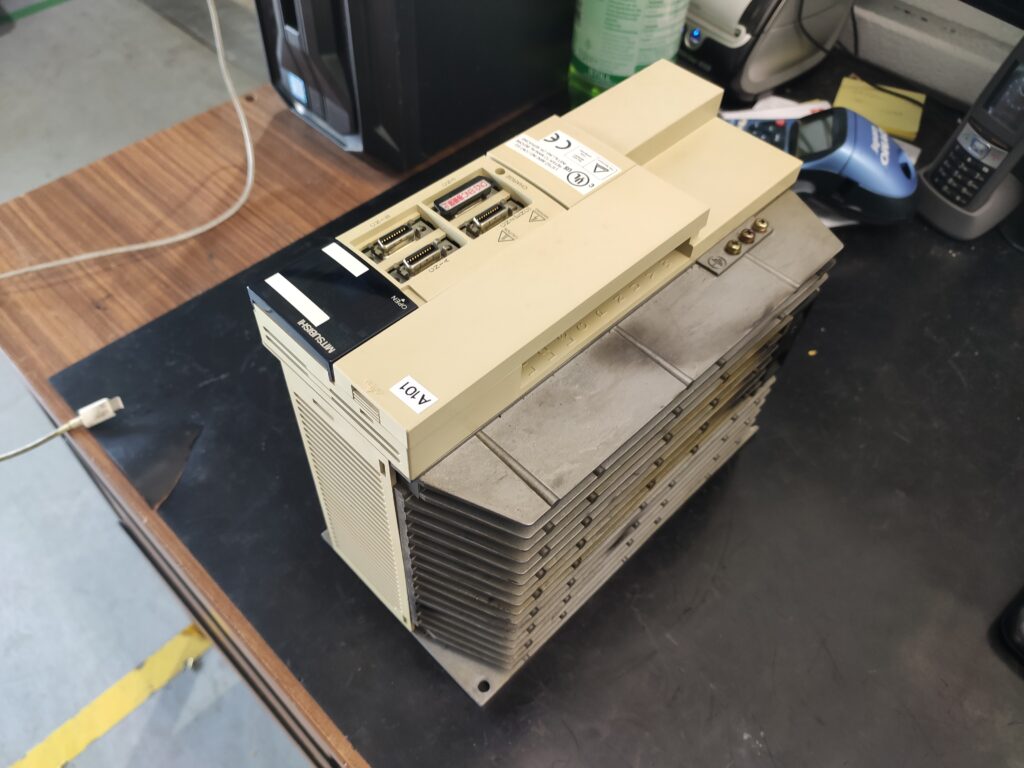
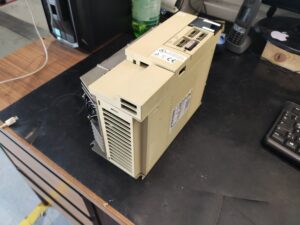
The supplied photographs document the unit before repair, its nameplate and the connected preliminary test. Video recordings before and after repair, together with an outgoing-condition recording of the unit, are also available. This allows the case to be presented from the incoming spindle drive through to the later test bench footage.
The component overview lists one RK812C control board, one RK826A power board and one power section. This identification supports the technical documentation. By itself, however, it does not establish which assembly contained the fault or which parts were replaced.
For diagnosing a temperature-dependent starting problem, a documented cold start and subsequent comparison with the warm condition are particularly informative. A professional examination may compare the supply, startup behaviour and operating readiness. Only the combination of fault observation and measurement provides a sound basis for narrowing down the cause.
Repair and subsequent functional testing
The video supplied as “after repair” documents the test arrangement with the connected unit and motor. The precise component cause, the list of replaced components and the complete test report are not included in the available case information. No specific component replacements, load values or test durations are therefore stated here as completed work.
For this fault, restarting after sufficient cooling is particularly relevant alongside operation on the test bench. A prolonged warm run can conceal the original problem. A meaningful final examination should therefore also address the conditions under which the drive previously failed. Whether such cold-start cycles were performed on this unit, and with what results, needs to be added from the test report.
What machine operators can learn from this case
If a spindle drive only functions after a waiting period or after warming up, this behaviour should be recorded. Useful information includes the time spent switched off, the state of the display, the ambient temperature and whether the spindle function is completely unavailable or becomes available after a certain period.
Clean ventilation paths, functioning cooling and intact connections remain important for reliable operation. When starting problems appear, however, maintenance should arrange a targeted examination of the startup behaviour. Repeated warming or leaving the unit switched on continuously does not eliminate an internal defect.
This Mitsubishi MDS-B-SPJ2-75 illustrates why repair assessment must consider more than running operation. How the unit starts from a switched-off, cooled-down condition matters just as much. That was precisely the abnormal behaviour that led the customer to leave his machine switched on for months.
Price, Lead Time and Further Information
Current information on the price and lead time of the Mitsubishi MDS-B-SPJ2-75 Spindle Drive Unit can be found on the corresponding product page.
Further information about our repair services for Mitsubishi servo and spindle drives is available in our manufacturer section.
📞 Please feel free to contact us if you have any questions about your Mitsubishi drive technology or a specific fault. Our team will be pleased to assist you with the technical assessment, repair and testing of your unit.
Technical Specifications
| Feature | Technical information |
|---|
| Manufacturer | Mitsubishi Electric Corporation, Japan |
| Model | MDS-B-SPJ2-75 |
| Device type | Spindle Drive Unit |
| Series | MDS-B-SPJ2 |
| Main input according to nameplate | 3AC 200–230 V, 50/60 Hz, 26 A |
| Second input entry according to nameplate | 3AC 200–230 V, 50/60 Hz, 0.3 A; check the terminal assignment against the manual |
| Output according to nameplate | 3AC, 26 A |
| Software marking | BND527W000A9 |
| Hardware version | E |
| Date marking | 03/04, reproduced unchanged from the nameplate |
| Heatsink | Side-mounted finned heatsink visible in the photographs |
| Power rating, dimensions, weight | Not stated on the supplied nameplate; no estimates made |
| Specific motor type and CNC model used in testing | Not unambiguously documented |
| Manual | MELDAS AC SPINDLE DRIVE MDS-B-SPJ2 SERIES SPECIFICATION MANUAL, BNP-B2164; supplied extract from Chapter 11, printed pages 11-4 to 11-26 |
Operating Environment and Compatible Equipment
Spindle drive for a suitable Mitsubishi CNC drive configuration. The specific motor, CNC version and hardware, software and parameter versions must be checked before replacement. Similar model numbers or matching connectors alone do not establish interchangeability. The available photographs do not permit a definitive compatibility approval for a particular replacement motor or a different board revision.
Functional Description
The unit supplies and controls the spindle motor. Power flows from the incoming supply through the DC bus to the three-phase motor output stage. CNC commands and feedback signals are evaluated for control. Monitoring functions cover DC bus voltage, current, speed and communication, among other factors. Internal auxiliary supplies are a prerequisite for correct electronic startup.
Components
The following identification comes from the supplied component list. Functions are described by assembly type without adding undocumented circuit details.
| Assembly | Designation | Quantity | Function | Inspection notes |
|---|
| Control board | RK812C | 1 | Control and signal processing | Investigate supply, startup behaviour and communication |
| Power board | RK826A | 1 | Power electronics assembly | Check associated supply, connections and drive signals against circuit documentation |
| Power section | Power section; no individual code supplied | 1 | Electrical power conversion for the motor | Electrical examination and functional testing on a suitable test bench |
Alarms and Troubleshooting
The table summarises ten alarms from the supplied MDS-B-SPJ2 extract. None of these codes has been confirmed as an alarm that occurred in this repair case. The measures are excerpts from the respective troubleshooting paths, not complete work instructions.
| Code | Original designation | Technical meaning | Possible cause | Check or action according to manual |
|---|
| 10 | UNDERVOLTAGE | PN DC bus falls to 200 V or less | Supply, phase loss, contactor or internal fault | Check contactor, charge indicator, input and PN voltage, p. 11-4 |
| 12 | MEMORY ERROR 1 | ROM checksum or RAM check error | Unit defect or electrical interference | Check repeatability, grounding and interference sources; manual specifies unit replacement for persistent fault, p. 11-5 |
| 13 | SOFTWARE PROCESS ERROR | Data processing did not finish within the required time | Internal fault or interference | Check repeatability, grounding and interference sources, p. 11-5 |
| 17 | A/D CONVERTOR ERROR | Current detection A/D conversion malfunction during initialisation | Internal fault or interference | Check power-up behaviour, grounding and interference sources, p. 11-5 |
| 21 | NO SIGNAL DETECTION (ENC) | A, B or Z signal error from the 1024-pulse/revolution orientation encoder | Encoder or signal connection | Check encoder connection and signal path according to manual, p. 11-6 |
| 23 | EXCESSIVE SPEED ERROR | Command/actual speed deviation greater than 50 rpm for 12 s | Wiring, parameters, load or feedback | Check U/V/W, parameters, acceleration time, load and detector cable, p. 11-7 |
| 24 | GROUND FAULT | Motor cable ground fault, detected at the Ready-ON instant | Motor cable or motor insulation | Check wiring and motor insulation, p. 11-8 |
| 30 | EXCESSIVE REGENERATION | Regenerative capacity limit reached | Resistor sizing, parameters or frequent starting/stopping | Check regenerative resistor, SP041 and operating cycle, p. 11-8 |
| 31 | OVERSPEED | Speed exceeds 115% of the value in SP017: TSP | Parameters, feedback or interference | Check operating mode, parameters, grounding and shielding, p. 11-9 |
| 32 | POWER MODULE ERROR | Excessive current in the power component | Load, wiring, motor, supply or internal fault | Distinguish occurrence before Ready-ON from after Servo-ON; check parameters, U/V/W, insulation and supply, p. 11-10 |
Diagnostic Notes on the Main Fault
- Confirmed symptom: no function when cold, operation after warming up.
- Specific alarm indication, subcode and measured values: not supplied.
- Customer account: machine left switched on for months to avoid the starting problem.
- External checks: incoming supply, connections, enable signals and machine conditions.
- Possible internal investigation areas: auxiliary supply, startup behaviour, capacitors and temperature-dependent connections. None of these establishes a component defect by itself.
- Recommended verification: document comparable cold- and warm-start conditions, associate measurements with each state and check repeatability.
- Distinction: a startup failure without a documented indication must not automatically be called Alarm 10, 12 or 17.
Preventive Measures
Check ventilation paths and heatsinks regularly, assess any installed fans according to their condition and include connectors in maintenance. Record changes in power-up behaviour early. Intervals depend on operating conditions and machine maintenance requirements. Examinations inside the drive unit must be carried out by qualified personnel, taking stored DC bus energy into account.