28.08.2025 by Viktor Siebert
Current Spikes, Noise and No Alarms – How We Repaired the MDS-B-SP-185 Spindle Drive Unit
A customer contacted us regarding unstable spindle behavior in a Mori Seiki CL-150 lathe. At low speeds, the spindle was noisy and unstable but no alarms were triggered. At higher RPMs, speed fluctuation became severe. Sporadic messages appeared on the CRT display:
- S04 Servo Alarm AR 0075
- S52 Servo Warning 00E8
These messages pointed to servo anomalies but did not clearly isolate the issue.
Upon arrival, we connected the MDS-B-SP-185 to our in-house spindle test bench, complete with load motor. Right away, current readings on the UVW phases stood out:
40 A – 60 A – 40 A,
even while the motor ran without load.
In contrast, our reference unit (MDS-A-SP-185) running the same motor showed only 12 A per phase.
No alarms, yet abnormally high output current. This strongly indicated:
- Faulty current sensing components
- Damaged power transistors (e.g., imbalance or leakage)
- Control board error in current feedback loop (RK311B)
The drive was disassembled, cleaned, and examined using our detailed spindle amplifier checklist. Notable issues:
- Dust accumulation on heat sink
- Capacitor aging (visual deformation)
- Discolored solder joints on the power board
We proceeded as follows:
- Tested RK124B-SP-185 power board and all IPM modules
- Verified signal integrity from HCPL current sensors
- Compared RK311B control board behavior with a known-good unit
- Replaced thermal compound and fitted new heat pads
- Installed a new fan and cleaned all ventilation paths
- Performed insulation testing up to 1000 V DC
- Ran a two-hour load test simulating production cycles
Final result: The repaired unit ran smoothly at all speeds with symmetrical current draw (~13 A per phase). No noise, no speed fluctuation. We documented the repair with:
- Thermal imaging report
- UVW current waveform logs
- Final test certificate including insulation resistance
Preventive Measures for Customers
- Regularly clean spindle cooling ducts and fan grilles
- Replace fans every 1–2 years
- Inspect or replace capacitors and current sensors every 10 years
- Perform insulation resistance tests during maintenance
- Optionally install temperature sensors on heat sinks
Conclusion
The MDS-B-SP-185 proved again how crucial precise current sensing is for spindle performance. Even with no alarms, hidden faults in the power circuit can cause major production issues. Our thorough diagnosis, structured workflow and preventative servicing restored this drive to OEM-level reliability: giving our customer peace of mind and full performance without replacement.
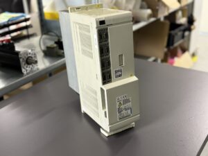
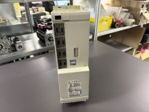
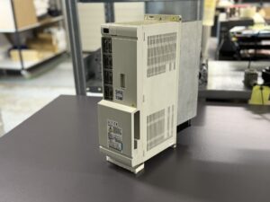
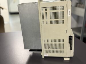
To mentioned Mitsubishi Drive: Mitsubishi MDS-B-SP-185 Spindle Drive Unit
More details about our Mitsubishi repair services can be found here:
Mitsubishi drive Repair by Industrypart
📞 Feel free to contact us with any questions about your Mitsubishi drive technology.
Our expert team is happy to help!
Technical Summary of the Unit
| Parameter | Value |
|---|
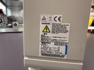
| Model | MDS-B-SP-185 |
| Device Type | Spindle Drive Unit |
| Input Voltage | DC 270–311 V / AC 200–230 V, 50/60 Hz |
| Rated Input Current | 76 A |
| Rated Output Current | 63 A |
| Cooling Method | Air cooling |
| Weight | n/a |
| Manual Reference | BNP-B8389 |
| Manufacturing Date | 06/1998 |
Application & Compatible Machines
This spindle amplifier is commonly found in CNC lathes and machining centers, including models like the Mori Seiki CL-150 with Mitsubishi MSC-803 control. It is engineered for high-speed spindle performance and is typically paired with MDS-B series power supplies.
Functional Description
The MDS-B-SP-185 is a dedicated spindle drive unit designed for dynamic spindle control in CNC environments. It processes speed commands, generates PWM spindle signals, and interfaces directly with the CNC controller. Stable power input and precise encoder feedback are essential for correct operation.
Alarm Messages & Troubleshooting
| Alarm | Meaning | Cause | Solution |
|---|
| 12 ME1 | Memory Error 1 | Fault in RAM/ROM on control board | Check/replace control board |
| 13 SWE | Software Error | Fault in software processing | Reset, reload firmware |
| 17 ADE | AD Converter Error | Fault in current detection AD converter | Check HCPL, current sense input |
| 21 NS2 | No Signal from Spindle Encoder | Encoder disconnected or cable broken | Check encoder, wiring |
| 31 OS | Overspeed | RPM exceeded maximum limit | Check setpoints, motor load |
| 32 PMOC | Power Module Overcurrent | Overcurrent in IPM circuit | Inspect transistor module |
| 38 TP1 | Protocol Error | Comm error with CNC controller | Inspect cables, control interface |
| 50 ON | Overload | Current exceeded safe operating level | Inspect fan, motor load |
| 52 OD | Excessive Position Error | Error in position feedback loop | Check PID tuning, sensors |
| 71 H | External Emergency Stop | External E-stop activated | Check safety circuit |
| 75 L | Overvoltage | Excessive DC voltage detected | Check power supply, braking unit |
Internal Components
| Component | Board Label | Qty |
|---|
| Control Board | RK311B / BN634A817G51 | 1 |
| Power Board | RK124B-SP-185 | 1 |
| Power Module | Power Unit (IPM) | 1 |