22.10.2026 by Viktor Siebert
Mitsubishi MDS-B-SP-150: Ab indication, startup stalls
The display remained at “Ab” and startup did not progress. This was the reported symptom when a Mitsubishi MDS-B-SP-150 spindle drive arrived at industrypart. Diagnosis identified faults in the internal power supply and on the main control board. Because the unit was heavily used, it received a comprehensive overhaul, thorough cleaning, replacement fans and subsequent testing. The case illustrates why a visible status indication must be distinguished from the fault actually established during diagnosis.
Technical data and spindle-drive function
| Item | Specification |
|---|
| Manufacturer | Mitsubishi Electric |
| Model | MDS-B-SP-150, Spindle Drive Unit |
| Nameplate power | 15 kW |
| Power input | 58 A, DC 270–311 V |
| Auxiliary supply | 0.2 A, 1 PH, 200/200–230 V, 50/60 Hz |
| Output | 49 A, 3 PH, 200 V, 0–833 Hz |
| Manual on nameplate | BNP-B3759 |
The electrical values come from the supplied nameplate. They are not measurements from the repair test. The 15 kW figure is the stated power rating; it does not establish suitability for every motor and machine combination. Output frequency must not be equated directly with mechanical spindle speed, which also depends on the motor and transmission.
The MDS-B-SP-150 belongs to the Mitsubishi MDS spindle system. It supplies and controls an associated spindle motor from a DC bus. A separate auxiliary supply supports the electronics. Power-circuit supply, internal electronics supply and CNC enable conditions are therefore distinct requirements. An illuminated display does not prove that all three are functioning correctly.
System environment, connections and interchangeability
CNC system, motor type, feedback, parameters and drive version must be considered together. A similar-looking MDS drive or an identical power rating alone does not establish interchangeability. The complete model designation, including any suffixes, together with the existing hardware and software versions, should accompany a repair or replacement enquiry. No specific machine-model or motor compatibility is claimed for this case.
The connection markings visible in the photographs distinguish the L+/L− DC bus, L11/L21 auxiliary supply and U/V/W motor outputs. Multipole front connectors belong to the control and feedback level; their actual assignment must be checked against the applicable wiring diagram. Feedback signals and CNC communication are not interchangeable. A matching connector shape does not establish a correct connection.
Documented assemblies
| Assembly | Documented designation | Quantity |
|---|
| Control board | RK311B / BN634A817G51 A | 1 |
| Power board | RK124B-SP-150 / BN634A805G51 | 1 |
| Power section | No additional identifier documented | 1 |
The control board handles control and signal-processing functions. The power board and power section participate in switching and delivering motor power. This list documents the assemblies present; it is not a list of complete boards replaced. Confirmed work comprises repair of the internal supply and main control board together with a comprehensive overhaul.
Reported symptom and workshop findings
| Observation | Classification |
|---|
| “Ab” indication; startup stops | Reported startup symptom |
| Internal power-supply faults | Established during diagnosis |
| Main control-board faults | Established during diagnosis |
| Heavily used and contaminated condition | Reason for comprehensive overhaul rather than a narrowly limited repair |
The drive did not progress beyond the observed startup state. The findings concerned two closely related areas: the supply must power the electronics reliably, while the control board handles initialisation and signal exchange. A fault in either area can disrupt startup. The stalled startup alone cannot identify which area is responsible.
Understanding the “Ab” indication
Mitsubishi MDS documentation associates “Ab” with an initialisation or waiting state related to NC startup. It must therefore not be translated automatically into “defective power supply”. When it remains unexpectedly, the CNC state, communication connection and system configuration must also be considered. In this repair, faults in the internal supply and on the main control board were actually established.
The sequence matters when describing a fault: does “Ab” appear before CNC power-up, remain afterwards, or occur only following a restart? A photograph of the complete display and the associated CNC message helps distinguish status from alarm. A label attached to the housing is not a substitute for an observed live indication.
Selected relevant alarms and warnings
The following selection is a general manufacturer reference, not a list of alarms observed in this repair. Its source is MELDAS 60/60S alarm manual BNP-B2201(ENG)L, section 1.3, pages I-14 to I-17. Distinguish the CNC prefix, axis identification and actual alarm number. Availability and response depend on drive version and configuration; the specific machine documentation remains decisive.
| Code | Meaning, paraphrased |
|---|
| 10 | DC bus voltage low |
| 12 / 15 | CPU/memory power-up check failed |
| 20 / 21 | Feedback signal missing |
| 31 | Excessive speed |
| 32 | Power-module overcurrent protection |
| 33 | DC bus voltage high |
| 34 / 36 | CNC data error / communication lost |
| 37 | Invalid initial parameters |
| 3A | Motor current excessive |
| 3B | Power-module overheating |
| 3D | Spindle fails to reach speed despite torque demand |
| 42 / 43 | PLG/encoder feedback fault |
| 45 | Fan stopped under relevant load |
| 46 | Motor overheating |
| 50 / 51 | Overload conditions |
The separate warning A6 indicates a stopped built-in fan (I-23). A warning and a shutdown alarm require different interpretation. “Ab” and “A6” are also different indications. The reported indication in this case was “Ab”.
Interpreting alarm groups during diagnosis
Voltage-related indications call for separate consideration of the main circuit and electronics supply. A low DC-bus voltage may have a different cause from an unstable internal supply. Communication indications require investigation of CNC state, connections, contacts and configuration. A communication fault does not automatically justify replacing the main control board.
Current and power-module indications call for examination of the complete motor-current path. Drive, motor cable and motor cannot be assessed in isolation. Feedback problems require a distinction between the signal source, wiring and evaluation circuitry. Temperature and overload indications additionally direct attention towards cooling, airflow, operating load and mechanics. These are general diagnostic relationships, not additional findings from this job.
Repair and subsequent testing
The faulty areas of the internal power supply and main control board were repaired. The heavily used drive was also comprehensively overhauled and thoroughly cleaned, and its fans were replaced. The work therefore addressed both the established electronic faults and clean cooling conditions.
The unit was tested after the work had been completed. The embedded video includes the supplied original test-stand footage, documenting an excerpt from the final checks. A specific test duration, defined load point or subsequent operation in the customer’s machine is not documented for this report and is not inferred from the footage.
Preventive care for older spindle drives
Filters and cooling paths should be checked at intervals appropriate to the actual workshop environment. Oil mist and dust can accumulate and impair heat removal. Changes in fan noise, reduced airflow and recurring temperature-related irregularities warrant professional inspection. A rotating fan alone does not demonstrate sufficient airflow.
Record startup behaviour and CNC messages before resetting the system. After changes to the machine or controller, document what was altered. Preserve the existing parameters and complete drive identification before selecting a replacement. Work inside the drive and on its power circuits requires qualified personnel and consideration of stored energy even after power has been removed.
Sources and image identification
Mitsubishi MELDAS AC Servo/Spindle MDS-A/B Specifications, BNP-B3759, spindle-system section IV; MDS-A/B status reference, III-17 for initialisation indication; MELDAS 60/60S Alarm/Parameter Manual, BNP-B2201(ENG)L, I-14 to I-17 and I-23. Electrical values and assembly identifiers: supplied original records. Photographs show differing serial identifiers. No common serial number is therefore stated; the nameplate photograph serves to identify model specifications.
Video from the workshop
Photo gallery
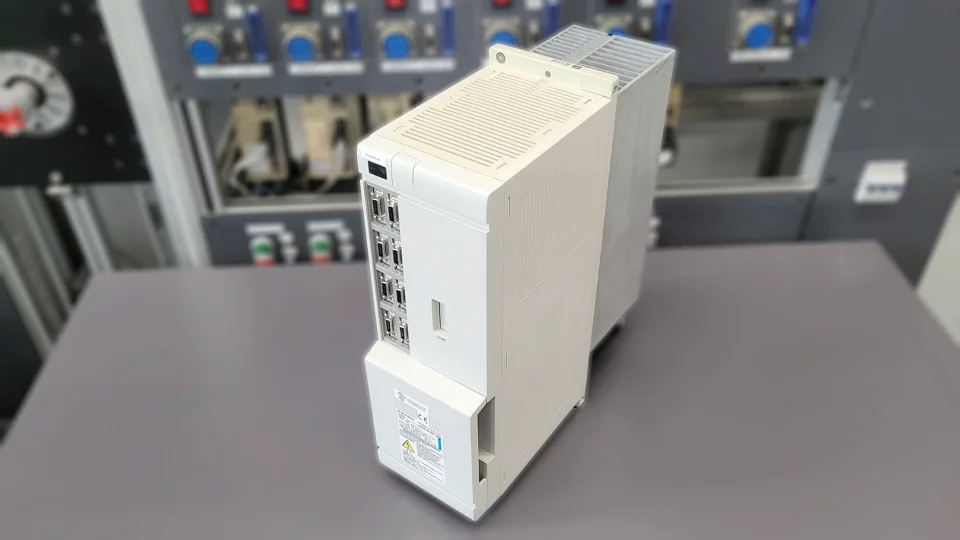 Mitsubishi MDS-B-SP-150 after overhaul
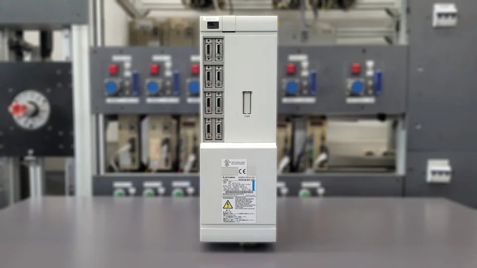 Front view after repair
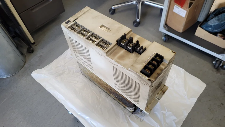 Supplied view before repair
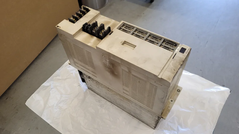 Side view before repair
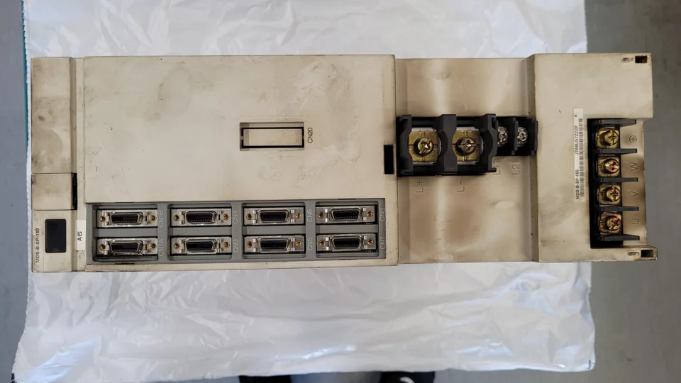 Front and terminals before repair
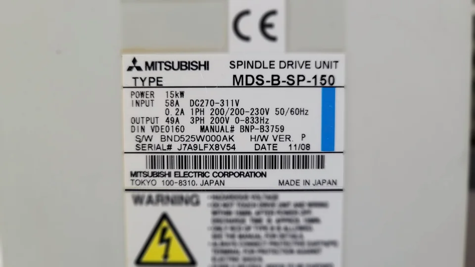 Nameplate for model identification
Repair enquiry
For a repair enquiry, please provide the complete model designation, a nameplate photograph, the displayed indication and a description of when the fault occurs. industrypart supports you with diagnosis, repair and preventive overhaul of industrial drive electronics.
Mitsubishi MDS-B-SP-150 Spindle Drive Unit in our shop
For more information about our repairs of Mitsubishi servo and spindle drives, visit our Mitsubishi repair service page.