24.04.2026 by Viktor Siebert
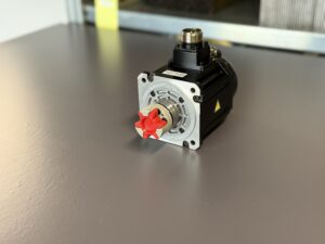
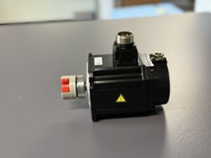
Mitsubishi HF-H75S with encoder fault after warm running
Initial situation and fault pattern.
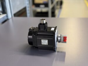
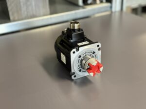
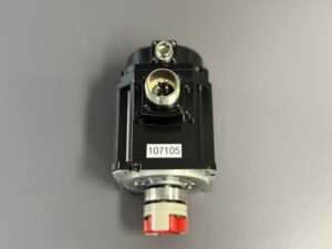
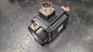
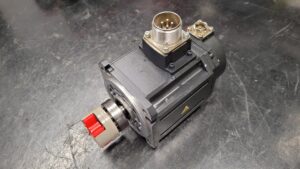
This Mitsubishi AC servo motor HF-H75S had a fault that was not clear at first in the machine. The motor was running with a Mitsubishi MDS-DH-V2-1010 drive. After start-up, the machine worked normally. Only after around two to three hours of machining did the encoder communication fail. After a cooling time of roughly thirty minutes, the machine could run again.
The customer had already checked the obvious parts. First, the cables were replaced. The fault remained. Then the servo drive was also replaced. That also made no difference. This made it clear that the cause was most likely inside the motor itself or in the encoder area.
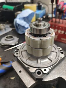
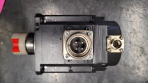
In our workshop, the motor was completely dismantled. The feedback area was checked especially carefully because the fault pattern strongly indicated a thermal encoder problem. When cold, such an encoder may still work. When the motor runs for a longer time and heat reaches the encoder area, communication can become unstable. The drive then reports an encoder or detector fault, even though the motor seemed to run normally before.
During the repair, the ball bearings were replaced, the connectors were renewed and the seals were replaced. The encoder was completely overhauled in our workshop. With this type of fault, it is not enough to only check cables or replace the drive. If the encoder fails when warm, the feedback system itself must be repaired and then tested under temperature.
After assembly, the motor was tested on the test bench. Low, medium and higher speeds were checked. It was not only important that the motor ran, but that the encoder signals stayed stable. The motor was started and stopped several times, operated for a longer period and checked for signal stability, running noise, temperature behavior and recurring alarms.
The fault did not return during the test. The feedback remained stable and the motor ran smoothly again after repair. This case shows clearly why sporadic encoder faults are often misdiagnosed. If cables and servo drive have already been replaced without success and the fault only appears after warm running, the encoder area inside the motor must be checked carefully.
What was important during the repair
| Area | Measure | Why it mattered |
|---|
| Motor | completely dismantled | Only this allows a proper check of bearings, seals, connectors and encoder area |
| Ball bearings | replaced | Worn bearings increase noise, vibration and thermal load |
| Connectors | replaced | Contact problems can cause sporadic encoder faults when warm |
| Seals | replaced | Protection against oil, coolant, moisture and dirt |
| Encoder | completely overhauled | The fault was most likely in the thermally unstable feedback system |
| Testing | test bench run at several speeds | Important for checking running behavior and signal stability |
| Warm running | longer test under temperature | The customer’s fault only occurred after two to three hours |
To mentioned Mitsubishi Motor:
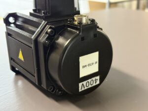
Mitsubishi HF-H75S-A48 AC Servo Motor
More details about our Mitsubishi repair services can be found here:
Mitsubishi motor Repair by Industrypart
📞 Feel free to contact us with any questions about your Mitsubishi drive technology.
Our expert team is happy to help!
Technical specifications
Motor
| Field | Value |
|---|
| Manufacturer | Mitsubishi Electric |
| Device type | AC servo motor |
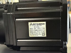
| Model designation | HF-H75S |
| Series | HF series |
| Power | 0.75 kW |
| Input voltage | 3AC 351 V |
| Output voltage | not separately specified |
| Rated current | 1.5 A |
| Control type | speed and position controlled servo operation via external servo drive |
| Feedback | encoder, depending on version OSA105S5 or OSA18 |
| Cooling | self cooling, closed housing design |
| Protection class | IP67 |
| Ambient temperature | not known, practical estimate approx. 0 to 40 °C |
| Mounting | machine axis, flange motor |
| Origin | Made in Japan |
| Product status | existing unit, not new |
Drive
| Field | Value |
|---|
| Manufacturer | Mitsubishi CNC |
| Device type | servo drive unit |
| Model designation | MDS-DH-V2-1010 |
| Series | MDS-D/DH |
| Power | not known, not safely derivable from the case |
| Input voltage | system dependent, via suitable supply unit |
| Output voltage | system dependent |
| Rated current | not known |
| Control type | digital servo drive with motor side detector evaluation |
| Feedback | motor side detector at CN2, optional machine side detector at CN3 |
| Cooling | forced cooling in the control cabinet |
| Protection class | control cabinet device, not known |
| Ambient temperature | manual refers to environmental checks, practical estimate approx. below 55 °C in the cabinet area |
| Mounting | control cabinet |
| Origin | not known |
| Product status | existing unit, not new |
Operating environment and possible applications
Typical machines are machining centers, machine tools, NC axes and similar positioning applications with high control accuracy. The MDS D DH works with a motor side detector at CN2 and can additionally evaluate machine side feedback at CN3. The alarm structure shows that the drive closely monitors motor feedback, external feedback, power section and supply.
Typical applications are feed axes, positioning axes and speed controlled servo axes. The practical requirements for the environment and control cabinet are clear. Clean cooling, low EMC load, proper grounding, shielded cable routing and separation of power and encoder cables. For communication errors, the manual explicitly names shielding, cable separation and single point grounding as relevant checking points.
Typical load factors that lead to defects are temperature build up during continuous operation, vibration, cable movement, contact aging, interference from motor cables routed in parallel, moisture or oil on connectors and general encoder aging. Preventive measures include regular connector checks, visual inspection for oil and contamination, clean cable routing, condition checks at the first sporadic alarms and a thermally realistic machine environment.
Functional description
The basic function of the system is precise control of an axis using feedback from the motor side detector. The MDS D DH continuously compares command value and actual value. The power section supplies the motor current, the control processes command and actual signals, and the feedback provides position and speed information. If the feedback fails, the drive can no longer regulate the axis cleanly and reacts with communication or detector alarms. Alarm 18 concerns the initial communication with the motor side detector, alarm 2F the communication error during operation, and 2B to 2E and 48 to 4B stand for detector error stages.
Enable and protection logic are safety relevant. Depending on the cause, the drive stops dynamically or in a controlled manner when alarms occur. Warnings are handled separately. Thermal monitoring concerns both the power section and the motor. Alarm 46 describes motor or detector overtemperature. This makes it understandable why a thermal fault at the encoder or in the nearby area may only become visible after a longer runtime.
For this repair case, exactly this interaction is decisive. The power section can basically be electrically intact, but the axis still fails if the feedback becomes unstable when warm. This explains why the drive partly still functioned and why replacing only the servo drive did not eliminate the fault.
Alarm messages and troubleshooting
| Alarm code | Description | Possible cause | Recommended measure |
|---|
| 18 | Main side detector: initial communication error | Incorrect detector type, cable fault, connector problem, detector defect, temperature or EMC problem | Check parameters, check connectors, measure cable, cross check detector, check grounding and shielding |
| 1F | Sub side detector: communication error | Interference, parallel routing with power cable, incorrect grounding, cable fault | Separate cables, check shielding, establish single point grounding, measure cable |
| 21 | Sub side detector no signal 2 | No ABZ signal, cable fault, detector defect | Check parameters, check connector and cable, replace detector |
| 22 | Detector data error | Scattered data from detector, loose mounting, vibration | Check detector mounting, evaluate vibration, follow subsequent steps from alarm 21 |
| 2B | Main side detector: error 1 | Detector specific fault at motor encoder | Evaluate detector and related alarm table |
| 2F | Main side detector: communication error | Communication interruption at motor encoder, shielding or grounding problem, cable fault, detector defect | Check connectors, improve cable routing, establish single point grounding, measure cable, check motor side |
| 32 | Power module error overcurrent | Power section overcurrent, motor short circuit, cable fault, feedback problem | Check motor power cable, measure insulation, check capacity and detector cable |
| 3A | Overcurrent | Excessive motor current, vibration, load jumps, insulation problem | Check vibration, check parameters, check power cable and motor insulation |
| 3B | Power module error overheat | Poor cooling, fan problem, contaminated cooling surfaces | Check fan and cooling surfaces, evaluate cabinet temperature |
| 46 | Motor overheat / thermal error | Motor or detector thermally too hot, cable fault, fan problem, overload | Check temperature curve, check connectors, evaluate load, cross test motor and drive |
| 50 | Overload 1 | Continuous overload of motor or drive | Check load, parameters and machine vibration |
| 51 | Overload 2 | High current command over a longer period | Check load, acceleration, feedback and collision |
| 61 | Power supply: power module overcurrent | Overcurrent in the supply unit | Check load condition and mains supply |
| 69 | Power supply: grounding | Motor or power cable to FG | Measure insulation, check for oil and contamination, replace motor or cable |
| 71 | Power supply: instantaneous power interruption | Mains interruption or voltage drop | Check supply, wiring and machine sequence |
| 77 | Power supply: power module overheat | Overtemperature in supply unit | Check fan, heat sink and cabinet cooling |
The source for the alarm codes and measures is the MDS D DH Instruction Manual. It describes both the alarm names and the checking steps for 18, 1F, 2F, 32, 46 and the supply codes 61 to 77.
Assembly overview
| Assembly | Functional designation | Function | Notes for testing or repair |
|---|
| Power section | servo drive power unit | Provides regulated motor current | Do not assume this as the cause too early in case of communication errors, first separate feedback |
| Control | digital servo control in the MDS-DH | Processes command values, protection functions and feedback | Check parameters, interference sensitivity and alarm history |
| Motor side feedback | encoder OSA105S5 or OSA18 | Provides actual values for position and speed | First testing focus for thermally delayed faults |
| Encoder cable | encoder cable with shielding | Transmits supply and communication data | Pay attention to separation from motor power, shielding and contact stability |
| Motor power circuit | U V W motor connection | Transfers power to the motor | Check insulation, connector condition and thermal load |
| Supply unit | power supply unit of the MDS series | Supplies DC bus and drive system | For codes 61 to 77, check supply, fan and mains quality |
| Connectors | motor and encoder connector system | Transition between motor, cable and drive | Watch for thermal contact problems and oil or dirt influence |
| Motor mechanics | bearings and rotor running | Ensures smooth running and low vibration | Vibrations can increase feedback errors |
| Cooling environment | motor environment and cabinet | Limits thermal load | Test continuous operation under real temperature conditions |
Typical defect causes and prevention
For this type of unit, typical defects are rarely caused by a single factor. Aging, temperature, vibration, cable influence and EMC often overlap. Especially with encoder and communication faults, the chain is often aged feedback, borderline shielding or grounding and additional temperature build up during continuous operation.
The risk increases with long machining times, warm control cabinet, contaminated connector areas, cable movement, lack of separation between power and encoder cable and mechanically unstable axes. Practical preventive measures are regular visual checks of connectors and cables, clean shield connections, fixed single point grounding, early reaction to sporadic detector alarms and thermal function tests instead of only short cold starts.
Proven technical solutions
For this fault pattern, clean separation between drive side and motor feedback has proven effective. First separate cable and drive, then specifically test the motor side encoder with temperature reference. Long term loaded tests, signal monitoring in warm condition and, if necessary, repair or replacement of the feedback unit are technically effective.
Measures that only shift symptoms are not sufficient. These include repeated resets, another cable replacement without findings, provisional reconnecting of plugs or general adjustment of control parameters without a clear cause. The repair becomes sustainable only when stable communication of the motor side encoder under operating temperature has been verified.