22.03.2026 by Viktor Siebert
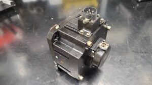
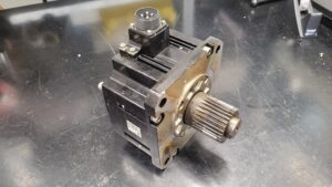
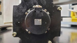
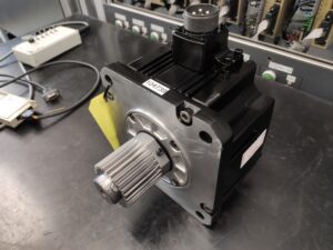
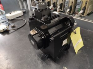
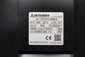
Mitsubishi AC Servo Motor HF-SP2024JKW04 with sporadic communication alarm caused by contaminated feedback system and advanced bearing damage
Initial situation and fault pattern.
A Mitsubishi AC servo motor HF-SP2024JKW04, operated on a Mitsubishi MDS-DH-V2-1010 drive, was delivered for inspection. During operation, a communication alarm occurred repeatedly. The fault pattern was not permanently present, but appeared irregularly. In practice, exactly this irregularity is technically noticeable, because it often does not indicate a complete failure of the power system, but rather a feedback or connection problem operating at its limit.
The motor still started and worked normally at times. Nevertheless, communication faults kept occurring between the motor feedback system and the drive. In addition, the motor was excessively loud during operation. Such acoustic changes are in many cases an early indication that not only an electrical problem but also a mechanical problem is present at the same time. In this case, the special feature was that both an intermittent fault message and a clearly changed running noise were present. The combination of interval fault and mechanical abnormality indicated a multilayered fault at an early stage.
Incoming inspection and initial diagnosis
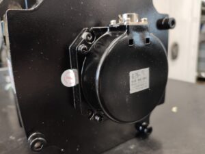
At the start, the usual incoming inspection was carried out with visual inspection, insulation assessment, and an initial functional classification. Even externally, there were indications of media ingress. After opening the motor, this suspicion was clearly confirmed. Considerable quantities of emulsion were found inside. This contamination affected not only the mechanical interior, but above all the motor side feedback system.
The insulation change was surprisingly small. This is technically important, because a motor can initially still appear relatively inconspicuous electrically despite liquid ingress, even though the actual fault is already developing in the feedback system or in the mechanical bearing arrangement. The reproducibility of the fault matched this. The motor did not stand out because of an immediate total failure, but because of sporadic communication problems in interaction with the drive.
In the initial limitation, three possible chains of causes were therefore considered. First, a signal problem in the feedback system. Second, mechanically caused instability in motor running. Third, a combination of media contamination, wear, and marginal signal quality. After opening, this third variant could be confirmed clearly.
Technical analysis
The main technical cause lay in the heavily contaminated feedback system. The emulsion had deposited itself in the sensitive detection area and massively impaired the optical evaluation there. In addition, the coding structure of the feedback system was partially mechanically worn away. This meant that the signal quality deteriorated not only because of contamination, but also because of actual material loss on the information carrying surface.
From this cause, the chain of effects is clear. Media ingress led to contamination of the feedback system. The contaminated and partially damaged coding impaired signal evaluation. This resulted in temporarily implausible or unstable feedback information. The drive interpreted these conditions as a communication or feedback problem and did not report the fault permanently, but whenever signal reserve, operating state, and disturbance level came together unfavorably. In the MDS D and DH series, such detector related faults are assigned to the main side detector alarms. For the OSA18 feedback system, CPU error and data error are assigned. In addition, a main side detector communication error is defined.
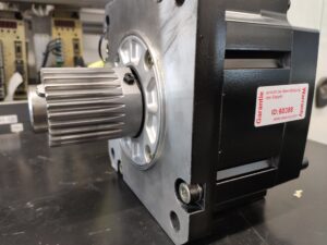
In addition, there was advanced wear of the bearing arrangement. The bearings were completely worn out and caused a significantly increased running noise. Mechanical instability has a directly negative effect on signal stability, air gap conditions, and vibration behavior in high resolution feedback systems. This means that the electrical fault was further aggravated by the mechanical condition. It is typical for such fault patterns that the motor continues to work surprisingly long even though the feedback system is already outside a stable reserve. That was exactly the case here. The fact that the motor still functioned at times under these conditions was more an expression of remaining residual function than of a healthy condition.
Repair measures and restoration
As part of the repair, the motor was completely disassembled, cleaned, and technically restored. All function areas affected by emulsion were decontaminated. The mechanical bearing arrangement was renewed, because the wear condition no longer allowed further operation. The feedback system was not only cleaned, but also functionally assessed with regard to the damaged coding structure. Since the information carrying surface already showed clear coding faults, simple cleaning was not sufficient as a sustainable measure. The affected feedback unit therefore had to be restored or functionally replaced.
In addition, the relevant connection areas, sealing surfaces, and transitions were checked in order to assess the cause of emulsion ingress. With this type of damage, not only repair of the motor is decisive, but also the prevention of renewed media ingress during later plant operation. For this reason, preventive notes regarding environment, sealing, cable routing, connector condition, and maintenance interval were included. In addition, insulation behavior, signal stability, and thermal behavior were checked again after restoration.
Final function test
The function test was carried out on the test bench under controlled supply conditions and with suitable feedback monitoring. Tested were switch on and switch off behavior, stable operation at low speed, medium speed, and in the range of the rated speed of approx. 2000 r/min. Low speeds are particularly important in such cases, because unstable feedback systems often become noticeable there through irregular running, counting faults, or sporadic disturbances.
In addition, behavior during repeated start stop sequences was tested. A thermal check, observation of signal stability, and monitoring for renewed communication or feedback abnormalities were also performed. After restoration, the motor showed a smooth running pattern, stable feedback signals, and no reproducible fault behavior. The previous excessive noise was eliminated. Operation on the test bench was fault free and reproducible.
Conclusion
The damage was a combined mechanical and electrical fault pattern. The actual main cause was emulsion ingress into the motor with massive impairment of the feedback system. The advanced wear of the bearing arrangement further aggravated the problem. This resulted in a sporadic communication alarm, even though the motor remained capable of running at times.
Technically, the case is typical of marginal feedback damage that does not immediately lead to total failure, but clearly endangers control stability and operational reliability. The repair is sustainable because not only the acute fault pattern was eliminated, but also the mechanical cause, the signal related cause, and the preventive boundary conditions were taken into account.
To mentioned Mitsubishi Motor:
Mitsubishi HF-SP2024JKW04 AC Servo Motor
More details about our Mitsubishi repair services can be found here:
Mitsubishi motor Repair by Industrypart
📞 Feel free to contact us with any questions about your Mitsubishi drive technology.
Our expert team is happy to help!
Technical specifications
| Field | Motor | Drive |
|---|
| Manufacturer | Mitsubishi Electric | Mitsubishi Electric |
| Device type | AC servo motor | Servo drive |
| Model designation | HF-SP2024JKW04 | MDS-DH-V2-1010 |
| Series | HF SP | MDS D and DH Series |
| Power | 2 kW | approx. suitable for 2 kW servo axis |
| Input voltage | 3AC 281 V | approx. 3AC 200 to 230 V class, system specific |
| Output voltage | motor specific and frequency dependent | servo dependent motor voltage |
| Rated current | 5.0 A | approx. 10 A class reference according to type designation, system specific |
| Control type | controlled AC servo motor operation | digital servo axis control |
| Feedback | Mitsubishi OSA18 | motor side feedback via CN2 |
| Cooling | self cooling, application dependent | internal cooling |
| Protection class | IP67 | approx. IP20 in the control cabinet |
| Ambient temperature | approx. 0 to 40 °C, application dependent | approx. 0 to 55 °C in the control cabinet, application dependent |
| Mounting | machine mounting | control cabinet mounting |
| Origin | Japan | Japan |
| Product status | unknown to discontinued, depending on market | unknown to discontinued, depending on market |
Operating environment and possible applications
The HF SP2024JKW04 motor is typically used in machine tools, handling systems, axis applications, and precise feed systems. In combination with an MDS DH V2 1010 drive, it is especially plausible in CNC related applications in which defined positioning, clean speed control, and stable feedback are required.
Typical production years of such systems are often in the range of approx. 2005 to 2018. They are used in installations with repeated cycle operation, dynamic acceleration, and in some cases demanding environments with heat, oil mist, emulsion, or conductive contamination.
For safe operation, clean control cabinet cooling, stable supply, proper shielding, and a dry environment in the area of connectors and transition points are important. Increased thermal load, condensation, insufficient strain relief, and poor sealing can significantly accelerate ageing of both the feedback system and the bearing arrangement.
Functional description
The motor converts the electrical power controlled by the drive into torque and speed. The drive handles current, speed, and position control. The motor side feedback system provides the drive with the necessary information about rotor position and motion status. Only if this feedback is plausible and stable can the control system work precisely.
In interaction, the system monitors enables, limit values, thermal states, and signal quality. The protective logic responds to overcurrent, overtemperature, communication faults, and detector related inconsistencies. In the MDS D and DH series, detector related faults of the motor side feedback system are assigned to alarms 2B, 2C, 2D, 2E, and 2F. For OSA18, CPU error and data error are specifically assigned, and a main side detector communication error is also defined.
These functions are safety relevant, because faulty feedback can lead to uncontrolled control deviation, positioning errors, or abrupt stop. Before opening or disconnecting connectors, always switch off the power supply, secure against restart, wait for the discharge time, and verify absence of voltage. Measurements on live parts may only be carried out by qualified electricians with suitable equipment and according to local regulations.
Alarm messages and troubleshooting
| Alarm code | Description | Possible cause | Recommended measure |
|---|
| 18 | Main side detector: Initial communication error | Initial communication with the motor side detector failed | Check parameter assignment, check connector condition, check detector cable, assess environmental interference |
| 2B | Main side detector: Error 1 | For OSA18: CPU error of the motor side detector | Check detector, check cable and connector, isolate fault to detector or drive |
| 2C | Main side detector: Error 2 | Motor side detector fault according to detector alarm table | Apply the same test steps as for detector fault analysis, assess detector and signal path |
| 2D | Main side detector: Error 3 | For OSA18: Data error of the motor side detector | Check detector function, check cable, isolate signal disturbance and internal data faults |
| 2E | Main side detector: Error 4 | Motor side detector fault according to detector alarm table | Apply the same test steps as for detector fault analysis, cross test detector or drive |
| 2F | Main side detector: Communication error | Communication data with the motor side detector faulty or communication interrupted | Check connectors, check cable routing, check shielding, check single point grounding, perform cable test |
| 36 | NC communication: Communication error | Communication with the NC was interrupted | Check NC communication and connection path |
| 61 | Power supply: Power module overcurrent | Overcurrent protection in the supply power module was triggered | Check load condition, supply capacity, and voltage level under load |
| 67 | Power supply: Phase interruption | Phase failure in the input power supply | Check incoming supply and wiring |
| 69 | Power supply: Grounding | Motor power cable is in contact with FG | Check motor power cable and insulation |
| 71 | Power supply: Instantaneous power interruption | Brief supply voltage interruption | Check mains supply, contactor sequence, and voltage dip |
| 72 | Power supply: Fan stop | Fan in the supply section stopped, causing overheating in the power module | Check fan operation, connector, and contamination |
| 77 | Power supply: Power module overheat | Thermal protection in the power module was triggered | Check cooling, ambient temperature, and load profile |
| 87 | Drivers communication error | Communication frame between drive units interrupted | Check internal communication between drive units and connections |
| 8A | Drivers communication data error 1 | Communication data 1 between drive units outside tolerance | Check communication path and affected unit |
| 8B | Drivers communication data error 2 | Communication data 2 between drive units outside tolerance | Check communication path and affected unit |
Module overview
| Module | Functional designation | Function | Notes on testing or repair |
|---|
| Motor power generation | electromagnetic drive system | generates torque from controlled electrical supply | Check winding condition, insulation, and thermal abnormalities |
| Motor feedback | optical position and speed detection system | provides position and speed information to the drive | Check for contamination, signal faults, and media exposure |
| Mechanical bearing arrangement | rotor side bearing guidance | ensures smooth running and defined mechanics | Check for noise, play, running pattern, and wear |
| Motor connection area | power and signal transition | connects the motor safely to the machine and drive | Check sealing, strain relief, and connector condition |
| Housing and sealing system | protection against environmental influences | reduces media ingress and supports heat dissipation | Check for leaks and corrosion traces |
| Drive power section | controlled power output to the motor | provides current and voltage for the axis | Check thermal load, ventilation, and fault memory |
| Drive control section | axis control and protective logic | processes setpoints and feedback | Check parameter plausibility and fault entries |
| Communication interfaces | internal and external data transmission | couples drive, CNC, and system components | Check connector condition, cable routing, and communication faults |
| Drive cooling | internal heat dissipation | keeps power section and electronics within permissible range | Check fan operation, air paths, and contamination |
| Supply connection | mains and DC link reference | stable energy supply of the drive | Check mains quality, phase condition, and connections |