13.06.2025 by Viktor Siebert
Haas Vector Drive 40HP 29-10081 Rev B: alarm 123 under load
Haas Vector Drive 40HP: shutdown under load with alarm 123
A Haas machine stopped unexpectedly during machining under load. The reported indication was alarm 123: Spindle Drive Fault. The customer initially suspected a spindle motor bearing problem. Our inspection of the Haas Vector Drive 40HP marked 29-10081 Rev B instead identified faults in the drive electronics and severely impaired cooling. This case illustrates why an alarm indication alone does not identify a particular failed component.
Identification and technical context
| Item | Documented information / interpretation |
|---|
| Manufacturer and device | Haas Automation, Inc.; spindle Vector Drive |
| Marking on the enclosure | 40 HORSEPOWER; 29-10081 Rev B |
| Power class | 40 HP, equivalent to approximately 29.8 kW. This does not separately establish continuous output, peak current or motor selection. |
| Control environment | Haas system; the alarm reference uses Classic Haas Control (CHC) documentation. |
| Cooling | Fan-assisted heat sinks and air passages |
| Electrical connection data | The enclosure marking shown does not establish a complete supply-voltage range or current limits. Device documentation and the machine wiring diagram govern. |
| Manufacturing year | Not established. The 2008 copyright notice is not evidence of the manufacturing year. |
| Interchangeability | Enclosure marking and power class alone are insufficient; hardware, connections, control, motor assignment and parameters must match. |
The visible number identifies this repair report. Before sourcing a replacement, compare all additional device identification and the machine documentation. A machine with a 40-HP spindle is not automatically compatible with every drive carrying the same power marking. Likewise, a mains-voltage specification for the complete machine must not be assumed to be the direct supply rating of the Vector Drive.
Function, energy flow and monitoring
Power electronics convert the supplied energy into the currents required by the motor. A DC link sits between the incoming supply and motor output. Capacitors buffer its energy, while the switching output stage creates the variable motor supply. The control commands the operating state, and feedback and protective functions supervise operation. Faults may therefore originate in the supply, power circuit, motor circuit or signal path.
During deceleration, the motor temporarily operates as a generator. The REGEN circuit connects the DC link to the braking load when required, dissipating energy as heat. A serviceable resistor alone does not establish that braking-energy control works: the switching devices and their control must also function. This distinction mattered in the present case.
Assemblies and diagnostic significance
| Assembly | Function | Finding in this case |
|---|
| Power output stage / IGBT modules | Switching motor currents | Overheating identified; modules replaced |
| Fan, heat sinks and air passages | Removing power losses as heat | Fan inoperative, heavy contamination |
| REGEN circuit | Controlled braking-energy dissipation | Internal circuit switched too late; overhauled |
| External REGEN load resistor | Converting electrical energy into heat | Functional when checked |
| Electrolytic and buffer capacitors | Energy buffering and stabilisation | All replaced during the overhaul |
| Control and monitoring electronics | Switching control and fault supervision | No verified circuit-board identifiers documented; none added |
Customer report and workshop findings
The customer reported shutdown under load with alarm 123. The suspected motor bearing damage had not been confirmed. Drive inspection revealed an overheated power stage, contaminated heat sinks and a stationary fan. Together these conditions impair heat removal and plausibly aggravate thermal stress on the electronics.
The original workshop report also records abnormal resistance readings at the outputs and delayed operation of the REGEN electronics despite a functional braking load. An idle DC-link reading above 360 V DC was also recorded. This isolated value is not a universal limit for all Haas versions. Without the associated supply, operating conditions and device-specific reference values, it cannot define a general fault threshold. We therefore do not present it as a universal diagnostic rule.
Narrowing down alarm 123
The point at which shutdown occurs is crucial: immediately at power-up, during acceleration, during cutting, while braking or only after warming up. Load-related failures can have electrical or mechanical origins. Assess the motor and its cable separately from the drive; an insulation or winding fault must not automatically be attributed to the output stage. Conversely, a suspected bearing problem does not explain away demonstrated electronic faults.
A general diagnostic approach considers the supply under operating conditions, motor circuit, connections, cooling and braking-energy circuit together. Feedback and control signals are included as appropriate for the actual machine. No encoder defect or specific machine-mechanical fault was documented in this case. These diagnostic areas describe systematic fault separation, not additional measurements claimed to have been performed.
Selected alarms relevant to the CHC environment
Only alarm 123 is documented as a customer report. The other codes are general references, not additional observed faults. The table uses brief paraphrases. Sources: Haas TG0157, “Symptom Table”, and TG0116. Check the control and software version.
| Code | Meaning | Context |
|---|
| 123 | Spindle drive fault | Separate drive and connected circuit |
| 119 | DC-link overvoltage | Supply / regeneration |
| 160 | Low AC input | Incoming supply |
| 200 | High-voltage supply overheating | Cooling |
| 292 | High-voltage supply fault | General indication |
| 444 | Excessive REGEN on-time | Supply / braking load |
| 647 | Shorted REGEN load | Braking circuit |
| 648 | Shorted DC bus | Drive REGEN circuit |
The previous “4444” notation has been corrected to 444. Alarm 200 is relevant to the cooling finding, but its actual occurrence was not confirmed. An alarm reference table does not automatically justify replacement of a particular component.
Repair and final testing
We replaced the failed fan and cleaned the entire cooling area, including the air passage. The IGBT modules were renewed and the REGEN circuit overhauled. All electrolytic and buffer capacitors were also replaced. The work addressed both the identified faults and important wear-prone areas of the electronics.
Final bench testing followed with simulated load behaviour. After successful testing, the unit was released for return shipment. The added original video shows a test run on a Haas machine. It documents the visible test situation; it does not replace a measurement report or independently establish a load or endurance test. We therefore do not claim a particular test duration or undocumented measurement results.
Practical preventive maintenance
Inspect cooling paths at intervals appropriate to the environment. Oil mist and dust can combine into adherent deposits. Clean-looking external grilles do not rule out contaminated heat sinks inside. Unusual fan noise, reduced airflow and repeated temperature-related shutdowns deserve early investigation.
The installation environment also matters after repair: clear air inlets and outlets, suitable cabinet ventilation and correct cable connections. Record recurring alarms with their timing, load condition and preceding machine operation. This helps distinguish thermal, supply-related and braking-related problems. High-voltage work requires qualified personnel; stored energy may remain after switching off.
Sources and scope
Haas TG0157: Vector Drive, CHC (15.10.2025); Haas TG0116: REGEN (14.10.2025). Online service documentation, “Introduction” and “Symptom Table” sections, without fixed page numbers; checked on 23 October 2026. Case-specific work comes from our existing workshop report. These manufacturer references are not individual connection or replacement approvals.
Original test video
Device views before repair
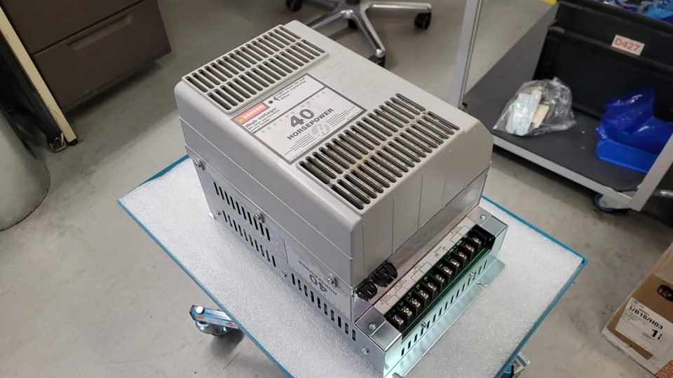 Angled view with terminal area before repair
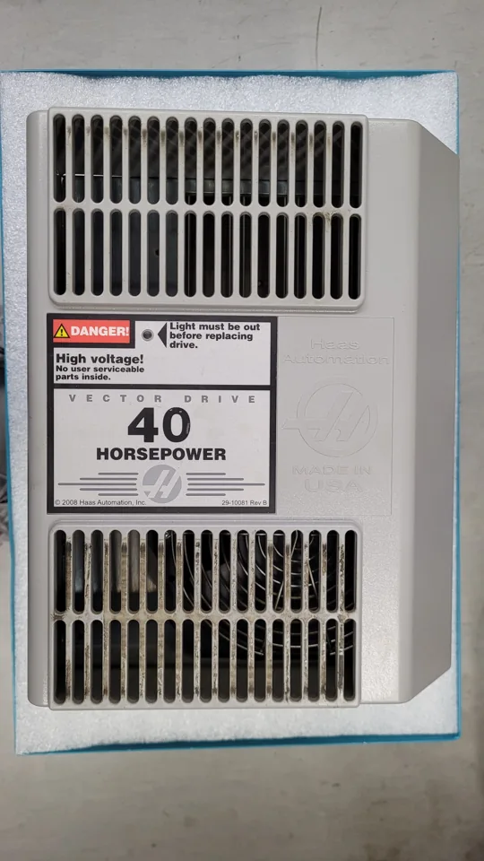 Front view with device marking before repair
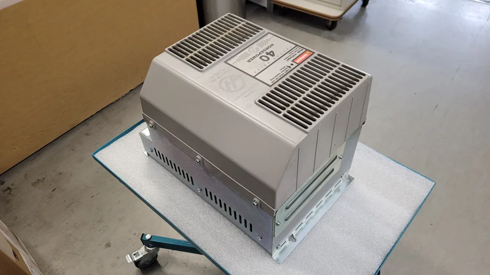 Side view before repair
Device views after repair
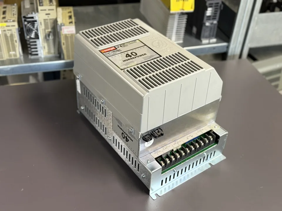 Main view after repair
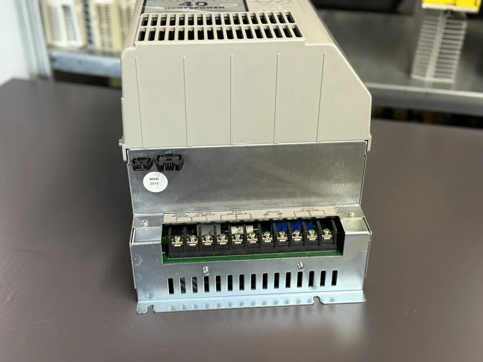 Terminal area after repair
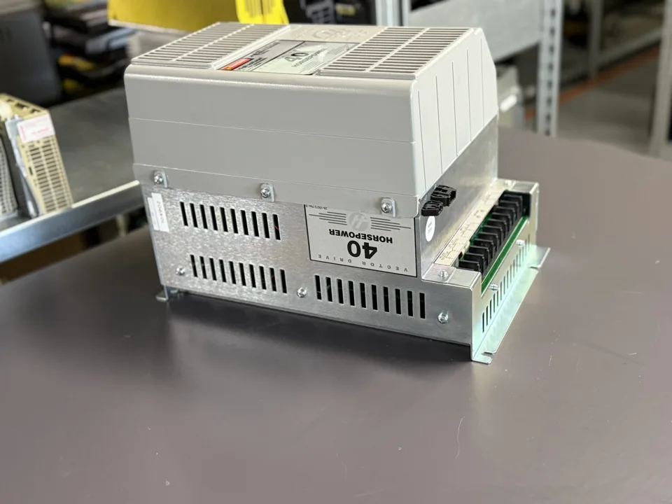 Side view after repair
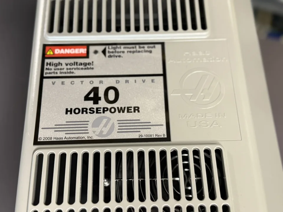 Device marking after repair
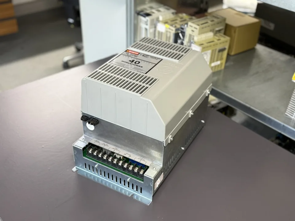 Additional angled view after repair
Request a repair
Does your Haas Vector Drive stop under load or report a fault? Send us the device identification, alarm number and a description of the operating sequence. Haas Vector Drive 40HP 29-10081 Rev B · Haas drives and motors: repair service