31.12.2025 by Viktor Siebert
Repair of a FANUC Servo Amplifier A06B-6096-H207 with CNC alarm 401, VRDY OFF and sporadic motor instability
The unit arrived with a field description that is often underestimated. The customer stated that the FANUC servo had no active alarm, but the connected motor sometimes produced strange noises, humming, and occasional light vibration. From an operator perspective this often looks minor, but these symptoms are typical for borderline cases where control quality, supply stability, and feedback no longer work together cleanly.
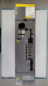
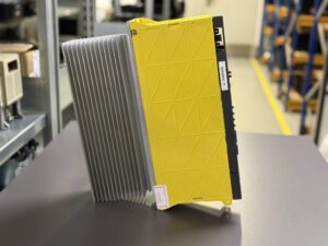
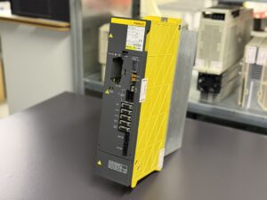
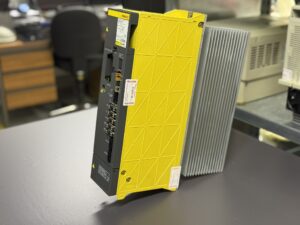
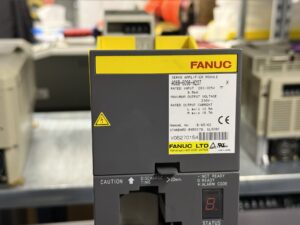
During incoming inspection we documented the amplifier, verified nameplate data, and performed a visual check. It was a FANUC Servo Amplifier Module A06B-6096-H207 with a DC link input of 283 to 325 V DC, rated power 8.5 kW, maximum output voltage 230 V, and two axis outputs rated at 12.5 A and 18.7 A. Then we applied the standard safety routine because DC link components can store energy. Only after the defined discharge time and verification measurements the unit was released for the next stage.
The key step was testing on our FANUC test bench. The goal is to reproduce the customer machine behavior as realistically as possible, but in a controlled environment. The bench includes a stable DC link supply, a defined enable chain, matching feedback, and a CNC environment that evaluates conditions such as VRDY consistently. On the first power up attempt the fault appeared immediately and reproducibly: the CNC displayed alarm 401 SERVO ALARM, X/Y AXIS VRDY OFF. The alarm occurred right away, before any meaningful axis motion could be started.
What was important for diagnosis: the amplifier itself did not show a clear alarm code. The display did not indicate a classic fault even though the CNC detected VRDY as missing or unstable. In practice this is explainable. VRDY is asserted only when internal startup conditions are met, auxiliary supplies are stable, and protection logic considers the state safe. If these startup conditions are unstable, the CNC can already react with VRDY OFF while the amplifier does not enter a clear alarm state with a dedicated code display.
We then followed our workshop standards strictly. First we excluded external causes, meaning test bench wiring, axis mapping, enables, feedback, and connector seating. After that, the analysis focused on typical aging points that can trigger such symptoms: unstable auxiliary supplies, aged DC link components, precharge path behavior, contact resistance, thermally stressed solder joints, and contamination around the cooling area. Especially when a motor previously hums or vibrates, it can indicate that current control is no longer clean because supply and measurement stability have degraded.
Because the fault was instantly reproducible on the test bench and clearly related to VRDY stability, we performed a preventive overhaul according to our standards. The goal is not only to remove one symptom, but to restore the stability reserves of the device.
The workshop process was as follows:
First the module was cleaned, including areas where conductive dust or oil mist can accumulate. Then assemblies and contact points were inspected, especially around the supply, DC link, and signal connectors. Aging critical components were evaluated according to our internal limits and replaced preventively in key areas that determine stable auxiliary rails and a healthy DC link. Thermally stressed solder joints in typical high load zones were reworked, and the cooling concept was checked so the amplifier returns to stable temperature behavior in continuous operation.
After reassembly the most important stage followed, the final verification on the test bench. We powered up again and observed the startup sequence. This time VRDY asserted cleanly, and CNC alarm 401 did not appear. Then we ran defined motion cycles, applied load simulation, and added a thermal phase to cover temperature dependent effects. We also checked the original symptom directly, motor sound and vibration, because smooth behavior is often the best indicator that control, sensing, and supply are stable again.
The timing also carried a symbolic side. Around the New Year you often count down outside, and in the workshop you count a different set of seconds. Stability of supply rails, clean feedback, repeatable tests, documented release. That is exactly how a unit should leave the building, especially when production will restart at the customer site.
The result was clear: after the preventive overhaul, the issue was resolved. VRDY remained stable and CNC alarm 401 no longer occurred on the test bench. The customer receives not just a short term fix but a module with addressed aging points, reducing the risk of follow up downtime and increasing machine availability. Repair is often the more sustainable choice compared to replacement because existing systems remain in operation without conversion or parameter risk.
Preventive Measures for the Customer
• Clean the control cabinet at defined intervals, typically every 3 to 6 months depending on the environment
• Verify airflow and filters, avoid heat buildup consistently
• Inspect connectors and shielding, especially motor power and feedback connections
• Separate routing of power and feedback cables, keep distance and implement clean grounding
• When early signs such as humming or vibration appear, test early before VRDY dropouts develop
• Plan preventive overhauls for older modules to mitigate aging in supply and DC link sections
Conclusion
This case shows that no alarm on the amplifier display does not automatically mean a healthy system. The CNC can react immediately with VRDY OFF if startup conditions and internal supplies are not stable. With reproducible test bench operation and a preventive overhaul according to standard, the FANUC A06B-6096-H207 returned to stable operation, well aligned with a reliable restart into the new year.
To mentioned Fanuc Drive: Fanuc A06B-6096-H207 Servo Drive Unit
More details about our Fanuc repair services can be found here:
Fanuc drive Repair by Industrypart
📞 Feel free to contact us with any questions about your Fanuc drive technology.
Our expert team is happy to help!
Device Description
| Parameter | Value |
|---|
| Voltage | Input (DC link): 283 to 325 V DC |
| Current | Rated output current: L axis 12.5 A, M axis 18.7 A |
| Power | Rated power: 8.5 kW |
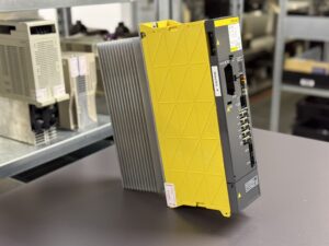
| Weight | approx. 7 kg |
| Dimensions | approx. 200 x 330 x 70 mm (H x W x D) |
| Type | FANUC servo amplifier module, 2 axes (L and M) |
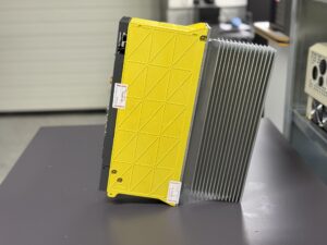
| Cooling | Heatsink, cabinet airflow concept, temperature dependent, depending on machine design |
| Control | FANUC CNC, enable chain with Servo ON and feedback via VRDY (Servo Ready) |
| Manufacturer | FANUC LTD, Japan |
| Production year | not specified |
| Manual reference | B-65162 |
Source for structure and requirements:
Operating Environment and Compatible Devices
The FANUC Servo Amplifier A06B-6096-H207 is a dual axis servo amplifier module used in CNC machine tools, typically machining centers and lathes. With two axis outputs, the module often fits axis pairs such as X and Y, depending on axis sizing and machine parameters.
Typical real world conditions:
• Supply via a stable DC link within 283 to 325 V DC
• Clean cabinet airflow to keep the heatsink and power section out of thermal limits
• Correct grounding and shielding, separated routing of power and feedback cables
• Stable enable signals and a reliable readiness feedback because the CNC releases motion only when VRDY is stable
The module is compatible within a typical FANUC environment with matching FANUC servo motors in the required current class and the corresponding feedback systems, depending on machine variant and control generation.
Functional Description
The module performs power conversion and control for two servo axes. The DC link is converted through a switched power stage into three phase motor currents, enabling precise torque and speed control.
Key functions in the field:
• Current control and torque generation for smooth motion, including dynamic movements
• Monitoring of DC link, power stage, auxiliary supplies, and temperature conditions
• Handshake to the CNC through enable signals and readiness feedback
• Protective functions against overload, overcurrent, overtemperature, and supply deviations
Important for the fault context: The CNC evaluates VRDY very early during startup. If internal supplies or startup conditions are not stable, the CNC can already react with VRDY OFF even if the module itself does not show a clear alarm code on the display. These borderline cases often start as humming, light vibration, or sporadic instability before a classic alarm becomes consistent.
Alarms and Troubleshooting
| Code | Fault description | Cause | Solution |
|---|
| SV001 | Overload alarm | Continuous overload, high friction, wrong parameters, thermal overload | Check mechanics, reduce load profile, improve cooling, verify parameters |
| SV003 | Abnormal current alarm | Short circuit, insulation issue, power stage or current measurement unstable | Insulation test motor and cable, check power stage, check connectors, test under load |
| SV004 | DC link overvoltage | High regeneration, braking resistor or regeneration issue | Check supply and regeneration, check braking resistor, review decel profile |
| SV005 | Precharge alarm (Series 15 A) | Precharge path does not reach target, components aged | Check precharge circuit, measure charging behavior, preventive overhaul |
| SV006 | Control power supply undervoltage, DC link undervoltage, power supply state alarm | Auxiliary supplies unstable, DC link drops | Measure auxiliary rails, check DC link, check contact quality |
| SV015 | Feedback disconnected alarm | Encoder cable open, connector loose, supply disturbed | Check feedback cable and connectors, verify shielding, replace cable if needed |
| SV023 | Fan stop alarm, overheat alarm | Insufficient cooling, fan issue, blocked airflow | Clean airflow paths, check fan, check cabinet cooling |
| SV027 | Invalid servo parameter setting alarm | Parameter inconsistency, wrong axis data | Verify parameter set, restore backup, align axis data |
| SV110 | Alpha pulse coder error alarm | Feedback fault, poor signal quality, noise | Check shielding, grounding, routing, verify encoder |
| SV114 | Rotation speed data error alarm | Implausible speed data, feedback issue | Check feedback path, check connectors and cable, run test cycle |
| SV115 | Pulse coder communication error alarm | Encoder communication fault, supply instability | Check supply and connectors, swap cable, reduce noise sources |
| SV116 | Precharge alarm (Series 15 B) | Precharge circuit or DC link aging | Check precharge, evaluate DC link, preventive overhaul |
| SV117 | Current conversion error alarm | Current measurement or analog section unstable | Check sensing paths, check supplies, verify on test bench |
This alarm overview is based on the provided FANUC Series 15 list.
Components
| Assembly | Designation / Code | Function |
|---|
| Power stage | IGBT power section | Generates motor currents from the DC link |
| Gate drive | Driver stage | Drives the power semiconductors |
| DC link | DC link capacitors | Energy storage and ripple smoothing |
| Precharge | Precharge path | Limits inrush, controlled charging |
| Auxiliary supply | Internal power supply | Supplies logic and measurement |
| Current sensing | Sensing section | Feedback for current control and protection |
| Interfaces | Power and signal connectors | Motor, feedback, enables, VRDY |
| Cooling | Heatsink and airflow | Removes losses as heat |
| Status display | 7 segment display | Status and alarm code display |