03.10.2025 by Viktor Siebert
Repair Story: Fanuc Power Supply Module A06B-6087-H130 with Alarm 01
A customer approached us with a Fanuc Power Supply Module A06B-6087-H130, which displayed alarm 01 immediately at power-up. For him, a lot was at stake: the machine was a central part of his production, and every hour of downtime meant lost orders. FANUC itself offered an exchange module for about €7,000, requiring the defective unit to be returned. The customer hesitated, saying: “My machine is important, but I prefer to wait two or three days for a repair rather than spend unnecessary money and have the old module scrapped.”
Fault symptoms and initial diagnosis
Alarm 01 means the power module (IPM Intelligent Power Module) detected overload, overcurrent or control voltage drop. When the unit was opened, several issues became visible:
- Cooling fan sluggish and intermittently failing
- Dust and oil contamination inside the cooling channel
- Clogged heatsink with reduced thermal capacity
- IPM showed unstable measurement values
Disassembly and cleaning
The module was fully disassembled. Dust, conductive particles and oil deposits were removed using compressed air, brushes and solvents. The heatsink was cleaned to restore full cooling efficiency.
Preventive replacement
To ensure long-term reliability, we replaced critical parts:
- New fan unit installed
- DC-link capacitors checked, suspicious ones replaced
- Connectors cleaned and coated with protective lacquer
- IPM module replaced with an original FANUC part
Test bench procedure
After reassembly, the unit was tested under realistic conditions:
- Initial check without load control voltages and signals verified
- Load simulation device operated under various load levels
- Thermal stress tests monitored semiconductor temperatures and fan currents
- Signal monitoring oscilloscope analysis of switching behavior and DC-link stability
- Long-term test several hours of continuous operation to ensure stability
All steps were documented in a detailed checklist and test report.
Risk without repair
If the customer had continued operation, the fan would have failed completely. The IPM would have overheated, possibly damaging not only the PSM but also connected servo and spindle amplifiers, causing extensive collateral damage and five-figure costs.
Result and customer benefit
The repaired module was reinstalled and the machine ran without error. The customer saved around 80% of the costs, extended the lifetime of his equipment and prevented a cascade of failures.
He also decided to introduce preventive maintenance for his other modules, shifting from reactive breakdown repair to proactive reliability.
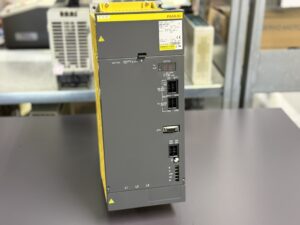
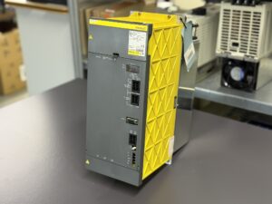
To mentioned Fanuc Drive: Fanuc Power Supply Module A06B-6087-H130
More details about our Fanuc repair services can be found here:
Fanuc drive Repair by Industrypart
📞 Feel free to contact us with any questions about your Fanuc drive technology.
Our expert team is happy to help!
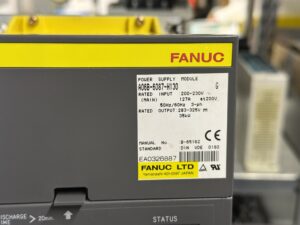
Device Specifications:
| Feature | Value |
|---|
| Manufacturer | FANUC LTD, Yamanashi, Japan |
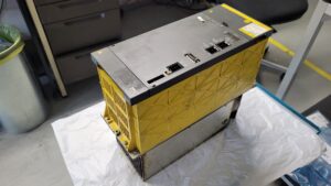
| Device type | Power Supply Module (PSM) |
| Model number | A06B-6087-H130 |
| Input voltage | 200–230 V AC, 3-phase, 50/60 Hz |
| Input current | 127 A at 200 V |
| Output voltage DC-Link | 283–325 V DC |
| Output power | 35 kW |
| Cooling | Forced-air cooling (fan unit, replaceable) |
| Weight | approx. 15 kg (estimated) |
| Dimensions | approx. 380 × 200 × 300 mm (estimated) |
| Control compatibility | CNC systems FANUC Series 0, 15, 16, 18, 21, Power Mate etc. |
| Certification | CE, UL |
| Manual reference | B-65165E/01 (Maintenance Manual) |
Application & Compatible Devices
- Typical machines: CNC machining centers, lathes, grinders, machine tools with FANUC control.
- Compatible controls: FANUC Series 0, 15, 16, 18, 20, 21, Power Mate.
- Compatible modules:
- FANUC α-Servo Amplifier Module (SVM)
- FANUC α-Spindle Amplifier Module (SPM)
- Use cases: Provides DC link power supply for servo and spindle amplifiers.
Functional Description
The Power Supply Module A06B-6087-H130 converts incoming AC voltage into a stable DC link (283–325 V). This DC power feeds servo and spindle amplifiers.
Features:
- Integrated protection against overcurrent, overload, undervoltage.
- LED indicators for operation and alarm states.
- Safety shutdown (MCC) in case of critical faults.
- Cooling control with fan monitoring and alarm.
Alarm Messages & Troubleshooting
| Code | Error Description | Cause | Solution |
|---|
| 01 | Overcurrent/overload in IPM | Fan failure, dust, overload, unbalanced supply | Check/replace fan, clean unit, check load, replace IPM if needed |
| 02 | DC link undervoltage | Low mains supply, rectifier failure | Check input voltage, inspect/replace diodes or power board |
| 03 | DC link overvoltage | Regeneration error, brake resistor fault | Check brake resistor, verify overvoltage protection |
| 04 | Fan alarm | Cooling failure | Check/replace fan |
| 05 | MCC contactor not switching | Control circuit fault | Check relay/contactor, verify wiring |
| 06 | Control power supply failure | PSU board failure | Inspect/replace PSU board |
| 07 | Overheat | Fan failure, ambient too hot | Clean, replace fan, check temperature |
| 08 | Insulation fault | Moisture, contamination | Perform insulation test, dry/clean unit |
| 09 | AC reactor overload | Wrong reactor specification | Verify correct reactor size, replace if necessary |
| 10 | IPM failure | Defective power module | Replace IPM |
Components
| Component | Description |
|---|
| Power board (IPM) | Main power circuit, AC→DC conversion, overcurrent protection |
| Control board | Signal processing, logic control, status indicators |
| Heatsink | Dissipation of power semiconductor heat |
| Fan unit | Forced cooling, critical for thermal stability |
| Power supply module | Auxiliary voltages (5 V, 15 V, 24 V) |
| Connectors | Input/output terminals, signal cable connections |
| Housing with LEDs | Mechanical protection and operating indicators |