29.09.2026 by Viktor Siebert
FANUC A06B-6141-H006#H580: Alarm 56 caused by fan failure and preventive overhaul
A fan is one of the less conspicuous components of a drive module. Nevertheless, its role is essential: heat generated during operation must be removed reliably. In this FANUC A06B-6141-H006#H580, a fan failure triggered an alarm on the machine. The unit arrived at industrypart for diagnosis and repair. Inspection confirmed a defective fan. In addition, our workshop identified signs of ageing in the power stage, which it associated with the prolonged marginal cooling performance.
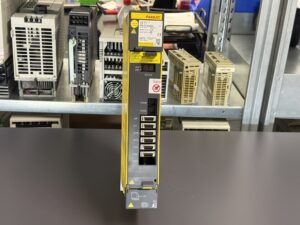
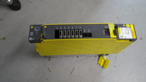
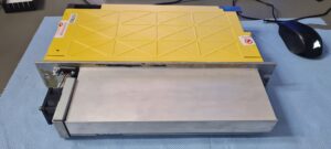
For this reason, the work went beyond replacing the failed fan. We completely overhauled the unit, replaced both fans and carried out preventive component replacement in accordance with our repair standard. The supplied recordings document the unit before and after overhaul and on the test bench.
What the alarm displays mean
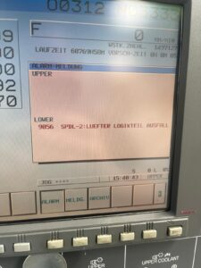
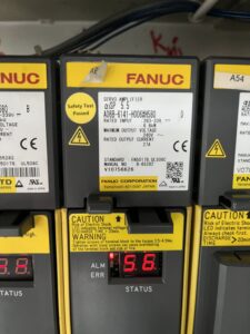
The amplifier display shows the number 56 with the ALM indicator illuminated. The machine control reports: “9056 SPDL-2: LUEFTER LOGIKTEIL AUSFALL”. Translated, this means fan failure in the logic section of spindle 2. Both the unit display and its assignment to the second spindle are therefore documented. “LOWER” belongs to the machine interface shown; it does not reliably identify a particular machine model.
FANUC maintenance manual B-65285EN/03 assigns alarm 56 to a stopped internal fan for the control section. The general alarm table uses SP0056. The machine photograph in this case displays 9056. We retain the actual machine display in the documentation and show it alongside the two-digit unit code.
This distinction matters during troubleshooting. Alarm 56 does not automatically indicate overheating or an already destroyed power semiconductor. It initially directs diagnosis towards internal cooling. According to the manual, a different fan alarm, 88, concerns the heatsink fan. These two messages must not be confused when selecting replacement parts or describing the cause. [1]
A spindle amplifier within the FANUC drive system
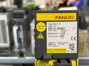
The nameplate carries the general designation “SERVO AMPLIFIER”. Its more specific model designation, however, is αiSP 5.5. This unit is therefore a spindle amplifier from the FANUC αi series. FANUC descriptions manual B-65282EN/06 also lists A06B-6141-H006#H580 among the αiSP spindle amplifiers. [2]
An amplifier of this kind supplies and controls the associated spindle motor. It processes CNC commands and converts energy from the DC link into the electrical power required by the motor. Motor feedback enables regulation. When choosing a replacement, the motor, feedback, parameters and unit configuration must therefore match, in addition to the ordering number.
The values on the supplied nameplate are clear: 283 to 339 volts DC at the power input, 6.8 kilowatts rated input power, a maximum output voltage of 240 volts AC and 27 amperes rated output current. The 6.8-kilowatt figure is explicitly an input value. It is not presented as mechanical motor output.
Diagnosis: The fan was genuinely defective
The workshop findings confirmed the alarm. One of the two fans was defective. According to our technicians, cooling had already been operating marginally for some time. Additional signs of ageing were found in the power stage.
There were therefore two related observations: a specific cooling-system failure and an abnormal condition of the power electronics. The workshop findings justified a comprehensive overhaul. That conclusion could not have been drawn from the alarm code alone. Alarm 56 does not identify which power-stage components may have aged or suffered damage.
When assessing such a case, it also matters whether the fault is permanent or intermittent. A fan may still start while operating unreliably. Unusual noise or uneven running should therefore prompt investigation. In this case, the diagnosis rests on the confirmed defect, not merely on an assumption based on the alarm text.
Why both fans were replaced
Both fans were renewed during the complete overhaul. The work therefore included the second fan, although only one fan had explicitly been diagnosed as defective. This is a preventive approach: the condition of the entire cooling system is considered in an ageing unit.
The actual stresses experienced by a fan depend on operating time, environment and contamination. The machine screen shows a runtime counter. However, this is not reliable evidence of the operating hours of this individual amplifier or its fans. We therefore use it neither to infer component age nor to specify how long cooling had been inadequate.
A similar appearance is also insufficient when selecting replacement fans. Physical design, electrical specification, connection and any monitoring function must suit the particular unit version. The part numbers of the replacement fans fitted in this case were not provided for this report and are therefore not added.
Complete overhaul to the repair standard
In addition to fan replacement, a complete overhaul was performed, including preventive replacement of the components specified by our repair standard. This statement refers to the defined overhaul scope. It does not mean that literally every individual electronic and mechanical part of the unit was replaced.
The additional power-stage findings made it sensible to consider the condition of the complete module. A new fan restores cooling, but does not automatically eliminate every existing sign of ageing. In this type of repair, we therefore consider the fault cause, possible associated effects and documented repair scope together.
An itemised list of replaced electronic components is not available for this article. We therefore do not name unconfirmed IGBT, IPM, PCB or capacitor types, or claim replacement of particular assemblies. The confirmed work comprises complete overhaul, renewal of both fans and preventive component replacement to the repair standard.
Documentation on the test bench
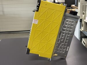
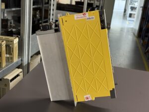
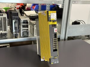
The supplied video shows the module in a connected test setup alongside FANUC control and motor equipment. The test bench can therefore be presented as part of the repair documentation. Additional recordings show the overhauled unit from several angles.
A video alone, however, does not provide complete load profiles or long-duration test results. No precise test duration, measurements, load levels or final test report were supplied for this case. We therefore do not invent operating hours, test speeds or temperature readings. Successful reinstallation at the customer’s site is also not yet confirmed by this material.
What operators can learn from this case
Fans and unobstructed airflow paths deserve the same maintenance attention as electrical connections. Early abnormalities should be investigated before they develop into permanent failure. The exact alarm on the unit and CNC helps narrow down the affected area.
Photographs of the complete nameplate, unit display and CNC message are particularly useful when requesting a repair. Whether the fault occurs immediately after switch-on or only once warm can also help diagnosis. Work inside an open drive must be undertaken by qualified personnel. The discharge times stated on the unit and verification of the absence of voltage must be observed.
This repair case shows why a fan alarm may justify closer examination of an ageing drive module. Fan failure was confirmed in the FANUC A06B-6141-H006#H580. The additional power-stage findings led to a complete overhaul, including both fans and preventive component replacement.
Price, Lead Time and Further Information
Please contact us for the repair price and lead time of the FANUC A06B-6141-H006#H580 αiSP 5.5.
Further information about our repair services for FANUC servo and spindle drives is available in the service section. These are the verified German destinations; an English destination was not verified.
📞 Please feel free to contact us with questions about your FANUC drive technology or a particular fault. Our team will assist with the technical assessment, repair and testing of your unit.
Technical Specifications
| Feature | Technical information |
|---|
| Manufacturer | FANUC |
| Model / ordering number | A06B-6141-H006#H580 |
| Alternative search spelling | A06B6141H006H580 |
| Size shown on nameplate | αiSP 5.5 |
| Unit type | Spindle amplifier; general nameplate designation SERVO AMPLIFIER |
| Version according to B-65282EN/06 | TYPE A, one spindle sensor input |
| Power input according to nameplate | 283–339 V DC; 6.8 kW rated input power |
| Maximum output voltage | 240 V AC |
| Rated output current | 27 A |
| Cooling in this repair case | Two fans, both replaced |
| Nameplate revision marking | Letter D |
| Control environment | FANUC; precise CNC type and machine not reliably established |
| Connected motor | Exact model number not documented |
| Year of manufacture, dimensions, weight | Cannot be reliably established from the supplied case information |
| Manual on nameplate | B-65282 |
| Research documents | B-65282EN/06; B-65285EN/03, spindle section |
Application Environment and Compatible Equipment
Used within the FANUC αi spindle drive system of CNC machine tools. The exact machine model in this case is not established. “SPDL-2” assigns the alarm to the second spindle; it does not indicate a second axis inside the amplifier. Before replacement, check the complete ordering number including #H580, hardware and software versions, motor configuration, feedback and parameter set. General interchangeability with A06B-6142 or an HV model is not guaranteed.
Functional Description
The module provides power-electronic control of the spindle motor from the DC link. The CNC supplies the operating command; feedback signals form the basis for regulation. The control and power sections perform different tasks and require reliable cooling. Internal monitoring reports detected faults on the module and to the CNC. The SERVO AMPLIFIER marking on the housing does not replace the more specific αiSP classification.
Components
The table describes the documented main structure, not a complete spare-parts list. No separate PCB photograph or component list is available.
| Assembly | Designation on PCB or module | Quantity | Function | Inspection or repair notes |
|---|
| Complete module | A06B-6141-H006#H580, αiSP 5.5 | 1 | Spindle drive | Completely overhauled |
| Fans | Individual part numbers not documented | 2 | Cooling | Both replaced; one defect explicitly confirmed |
| Power stage | Individual designation not established | Not documented | Power conversion for the motor | Ageing reported by workshop; no invented IGBT/IPM number |
| Control electronics | Individual designation not established | Not documented | Regulation, communication and monitoring | Internal fan fault reported by alarm 56 |
| Heatsink | No readable ordering number | 1 visible | Heat dissipation | Maintain clear cooling paths |
| Front display | STATUS, ALM, ERR | 1 | Status and alarm display | Photograph documents 56 |
Alarm Messages and Troubleshooting
Selection from the αi spindle section of B-65285EN/03, chapters 2.1.2 and 3.4. No servo-axis or power-supply codes. The CNC display may vary by control. Only 56 and the photographed 9056 are documented in this case. English short descriptions in this table are editorial summaries; the complete original names are in the linked alarm list. [1]
| Code | English short description | Technical meaning | Possible cause | Check / action, summarised |
|---|
| 01 | Motor overheating | Motor too hot | Cooling/load | Check motor cooling |
| 02 | Speed tracking fault | Speed deviation | Load/parameters | Check load and parameters |
| 03 | DC fuse fault | DC-link fuse | Short circuit | Check motor cable and module |
| 06 | Thermal sensor fault | Temperature measurement fault | Sensor/cable | Check feedback cable |
| 07 | Overspeed | Excessive speed | Sequence/module | Check sequence |
| 12 | Power-module protection | Overcurrent/IPM fault | Short circuit/cooling | Check motor, wiring and cooling |
| 18 | Program checksum fault | Program check failed | Electronics | Replace control PCB/module |
| 24 | Serial data fault | Data transfer fault | Interference/cable | Check cable routing |
| 56 | Internal cooling fan stopped | Internal fan stopped | Fan/connection | Check PCB seating; replace fan/module |
| 88 | Heatsink fan failure | Heatsink fan stopped | Fan | Replace heatsink fan |
Diagnostic Notes on the Main Fault
Unit display: 56 with ALM. Machine display: “9056 SPDL-2: LUEFTER LOGIKTEIL AUSFALL”. No further subcodes or stored measurements were supplied. The exact original name of the main alarm is “Internal cooling fan stopped”.
In addition to the internal fan, the manual identifies an incompletely seated control PCB or its connection to the power section as a troubleshooting point. This is a general diagnostic possibility, not an additional finding on this unit. Here, the workshop confirmed a defective fan. Alarm 88 must be distinguished from this. Power-stage ageing was identified separately and was not inferred from alarm 56. [1]
Preventive Measures
Regularly assess fan condition, noise, airflow paths and contamination. If alarms occur intermittently, record the complete display and operating state. Base maintenance and spare-parts selection on the unit version, environment and operating conditions. Do not infer a universal replacement interval from this single case. Do not bypass protective functions. Work only after proper isolation, sufficient discharge and verification of the absence of voltage.