01.06.2025 by Viktor Siebert
Real Repair Story Fanuc Servo Amplifier A06B-6114-H205
Just recently, we received a Fanuc A06B-6114-H205 Servo Amplifier from a customer reporting recurring failures, random axis loss, and error code “8” continuously displayed. The unit had previously been evaluated by another service provider – without success.
We performed in-depth diagnostics and identified faulty power output stages and inconsistent current monitoring. The unit underwent a preventive overhaul: replacement of power IGBTs, aged capacitors, and a malfunctioning temperature sensor. After cleaning and load testing on our Fanuc test stand, the unit was returned fully functional.
This is how the device was repaired at our facility. Our technicians performed the following measures:
Condition Analysis & Thermography: Identification of thermal hotspots on circuit boards and power components. Cleaning: Removal of dust, oil, and circuit board residues in an ultrasonic bath. Replacement of Defective Components: Exchange of all IGBT modules, driver transistors, and sensitive current sensors. Preventive Overhaul:
- Renewal of all electrolytic capacitors (especially in the DC link).
- Replacement of the relay contacts for brake management.
- Inspection and, if necessary, replacement of connectors.
- Renewal of the gate resistors on the driver stages. Test Run under Nominal Load on our specially developed Fanuc test stand. Documentation & Test Report: for complete traceability and customer assurance.
The Result: stable continuous operation for over 3 hours, all internal temperatures within the normal range, no more voltage or current deviations.
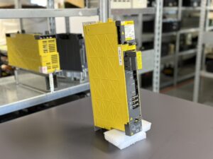
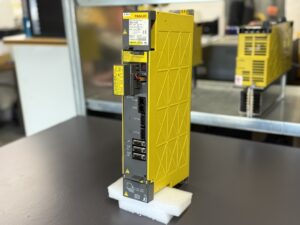
To mentioned Fanuc Drive: Fanuc A06B-6114-H205 Servo Amplifier
More details about our Fanuc repair services can be found here:
Fanuc drive Repair by Industrypart
📞 Feel free to contact us with any questions about your Fanuc drive technology.
Our expert team is happy to help!
Technical Specifications
| Parameter | Value |
|---|
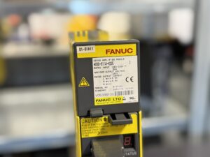
| Model Number | A06B-6114-H205 |
| Rated Input Voltage | 283 – 339 V AC |
| Output Voltage | 240 V |
| Output Current Axis L | 6.5 A |
| Output Current Axis M | 6.5 A |
| Weight | approx. 3.9 kg |
Fanuc A06B-6114 series devices are Servo Amplifier Modules (Alpha-i SVM). Failures and malfunctions in these devices are usually indicated by alarm codes on the device itself or on the CNC controller. Based on frequent mentions in technical documentation and specialist forums, the most common errors include:
Common Alarm Codes and Causes of Errors:
- Alarm Code 1 or F: Fan Malfunctions
- Meaning: The internal fan of the amplifier or the heatsink cooling fan has failed.
- Possible Causes: Defective fan, fan blocked by foreign objects, loose fan cable connection. This can lead to overheating.
- Alarm Code 2: Control Power Supply Undervoltage
- Meaning: The 5V control voltage for the amplifier is too low.
- Possible Causes: Problems with the power supply unit (PSM), defective cables or connections, internal fault in the amplifier.
- Alarm Code 5: DC Link Undervoltage (LVDC)
- Meaning: The voltage in the DC link of the amplifier is too low.
- Possible Causes: Problems with the main power supply, defective Power Supply Module (PSM), fault within the amplifier itself.
- Alarm Code 6: Inverter Overheat
- Meaning: The power module (IPM) or the amplifier is overheated.
- Possible Causes: Failure of the cooling system (see Alarm 1/F), motor overload, insufficient ventilation in the control cabinet, high ambient temperatures.
- Alarm Code 8, 9, A (with or without a dot): Overcurrent or IPM Alarm
- Meaning:
- Without a dot (e.g., 8): Overcurrent in the corresponding axis (L, M, or N).
- With a dot (e.g., 8.): IPM (Intelligent Power Module) alarm in the corresponding axis. This often indicates an internal fault in the power module, possibly due to overcurrent, overheating, or a short circuit.
- Possible Causes: Short circuit in the motor or motor cable, defective motor, mechanical blockage of the axis, faulty amplifier (IPM).
- Alarm Code P: Communication Error
- Meaning: Communication error between the amplifier and the CNC controller or another module.
- Possible Causes: Defective fiber optic cables (FSSB), loose connections, incorrect settings, defective controller or amplifier board.
- Alarm Code U or L: FSSB Communication Error
- Meaning: Error in the High-Speed Serial Bus (FSSB) communication, which is responsible for the connection between the CNC and the drives.
- Possible Causes: Problems with the fiber optic cables (damage, kinks, contamination of the connectors), defective FSSB interfaces on the CNC or the amplifier.
General Sources of Errors That Can Lead to Various Alarms:
- Power Supply Problems: Unstable input voltage, defective power supply units.
- Wiring Issues: Loose connections, damaged cables, short circuits.
- Cooling: Insufficient cooling in the control cabinet can lead to overheating alarms.
- Motor Problems: Defective motors (winding shorts, bearing damage) can trigger overcurrent alarms.
- Mechanical Problems: Stiffness or blockages in the mechanics can lead to overload and overcurrent.
It is important to note that precise diagnosis often requires systematic troubleshooting, which may include checking cables, voltages, motor condition, and replacing components. For recurring or serious errors, consulting a qualified Fanuc service technician is advisable.