02.03.2026 by Viktor Siebert
FANUC A06B-6096-H301: Alarm b. on the servo module and 449 INV. IPM ALARM on the CNC
Initial situation and fault pattern.
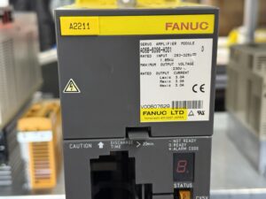
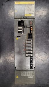
A FANUC AC Servo Amplifier module A06B-6096-H301 was delivered. According to the fault description, the drive could be switched on, but axis motion was not possible. After switching on, the code “b.” appeared reproducibly in the status window on the servo module. At the same time the CNC reported “449 X/Y AXIS: INV. IPM ALARM”. The alarm occurred directly when attempting to enable the axes. Further tests were blocked by this.
Technically, the dotted indication on the drive is notable. With these assemblies, this display stands for an internal protection case in the power path and not for a simple parameter entry. This means an early distinction is required between an external cause (motor, cable, supply) and an internal fault in the module.
Incoming inspection and initial diagnosis
Before any work: switch off power, secure against being switched back on, wait for the discharge time and verify zero voltage. A discharge time of more than 20 minutes is marked on the module.
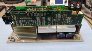
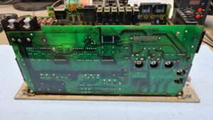
The visual inspection showed significant contamination in the air path and indications of reduced airflow. In addition, there were signs of prolonged thermal stress. Connections and housing were checked for loose fit, mechanical damage and moisture.
At the test bench the fault pattern was reproduced. The module started, but immediately went back into the alarm state when enabling. The code “b.” was stable and repeatable, independent of further command.
Technical analysis
The FANUC Servo Maintenance Manual describes that IPM alarms are displayed as 8., 9., A., b., C., d. or E. in the LED window. The code “b.” corresponds to an IPM alarm for the L and M axes. This matches the drive code to the CNC message for two axes, here X and Y.
An IPM alarm means that the internal protection of the power module trips. Possible causes include overcurrent, a supply disturbance or overheating. As an initial differentiation, the manual mentions a waiting time, because a pure overheating condition does not necessarily occur again after cooling down. If the alarm remains, the cause is more likely seen in protection operation due to overcurrent or supply fault, or in a defect in the amplifier.
From the finding chain a plausible picture resulted: contamination and a worn fan increase component temperatures. Under load, losses rise, protection reserves become smaller and the electronics operate closer to the limit more often. Over a longer period this can lead to overload and consequential damage in the power module as well as in its drive control. The end state is then an immediate IPM alarm already when enabling.
Repair measures and refurbishment
The repair was carried out as a preventive complete overhaul. First, cleaning and restoration of the air path were performed. The cooling unit was renewed.
In the next step, the functional assemblies in the power stage and in the drive control were reworked and replaced as required. In addition, contact points, connector areas and internal connections were checked, reworked and secured. Finally, the supply path and the diagnostic functions were stabilized so that protection thresholds and feedbacks operate reproducibly again.
Final functional test
The functional test was performed on the FANUC test bench with suitable DC link supply and load simulation. Tested were on off behaviour, enable, command changes and stable control at low, medium and higher speeds. Under load, current consumption and thermal behaviour were monitored for several hours.
The result was stable and reproducible. The alarm b. no longer occurred, and the CNC no longer showed an INV. IPM message.
Conclusion
The fault was a progression of weakening cooling and the resulting thermal overload up to a protection case in the power path. The combination of CNC alarm 449 and drive code “b.” shows that the amplifier could no longer ensure safe operation of the affected axis channels. Through the complete overhaul with focus on cooling, power stage and drive control and through the several-hour load test, the function is restored and the repair is sustainably secured.
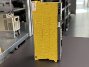
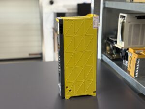
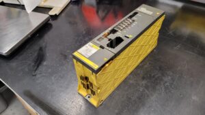
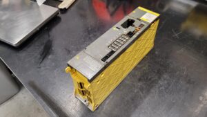
To mentioned Fanuc Drive: Fanuc A06B-6096-H301 Servo Drive Unit
More details about our Fanuc repair services can be found here:
Fanuc drive Repair by Industrypart
📞 Feel free to contact us with any questions about your Fanuc drive technology.
Our expert team is happy to help!
Technical Specifications
| Field | Value |
|---|
| Manufacturer | FANUC |
| Device type | AC servo amplifier module (servo amplifier module) |
| Model designation | A06B-6096-H301 |
| Series | AC Servo Amplifier |
| Power | 1,85 kW (nameplate) |
| Input voltage | ca. 283 to 325 V DC link (nameplate) |
| Output voltage | max. 230 V AC (PWM) (nameplate) |
| Rated current | 3,0 A per axis channel L, M, N (nameplate) |
| Control type | Digital servo control via CNC, PWM current control in the amplifier |
| Feedback | Pulse coder, depending on the motor usually incremental, ca. 2500 to 10000 pulses/rev |
| Cooling | Forced air, integrated fan |
| Protection rating | ca. IP20, installation in control cabinet required |
| Ambient temperature | ca. 0 to 55 °C in the control cabinet, derating at high temperature |
| Mounting | Control cabinet mounting, vertical, free air path and filters required |
| Origin | Japan (nameplate: FANUC LTD, Yamanashi) |
| Product status | discontinued or legacy, replacement often via repair or refurbishment |
Operating environment and possible uses
Typical use is as an axis amplifier in CNC machine tools and handling systems. Such modules are often found in machines from ca. the late 1990s to ca. 2010, depending on the control generation. In operation, stable control cabinet cooling, clean airflow and sufficient reserve for ambient temperature are decisive. Filter mats and fans must be treated as a maintenance item, because thermal overload in this assembly directly influences the service life of the power stage.
Functional description
The module is supplied from a DC link and generates a controlled, three-phase motor supply from it. The CNC provides enable and commands, while the amplifier regulates motor current and monitors protective functions. The control loop is closed via the motor feedback, typically via a pulse coder.
Safety relevant are enable logic, current limiting, overtemperature monitoring and monitoring of the supply. In impermissible conditions the power stage is blocked and an alarm is issued. The discharge time of the DC link must be observed. Before opening or unplugging connectors: switch off power, secure against being switched back on, wait for the discharge time and verify zero voltage. Measurements on live parts only by a qualified electrician.
Alarm messages and troubleshooting
| Alarm code | Description | Possible cause | Recommended measure |
|---|
| 449 (CNC) | INV. IPM ALARM X/Y | Protection in the power path has tripped, often overcurrent or overheating | Check alarm history, assess cooling and control cabinet temperature, further measurements only by a qualified electrician, then professional diagnosis on the test bench |
| b. (LED) | IPM alarm L and M axis | Internal protection case on two axis channels | Check axis assignment, narrow down external causes, check module internally |
| 8. (LED) | IPM alarm L axis | Protection case on one axis channel | Have motor cable and motor checked for insulation, channel-specific diagnosis |
| 9. (LED) | IPM alarm M axis | Protection case on one axis channel | As above, additionally check connector contact and shielding |
| A. (LED) | IPM alarm N axis | Protection case on one axis channel | As above, check axis allocation in the system |
| 1 (LED) | Fan stopped alarm | Fan blocked, contaminated or supply interrupted | Check air path, check fan function, service filters, repair fan or module as required |
| 2 (LED) | Control power supply undervoltage | Control auxiliary voltage too low | Check power supply unit and connectors, measurement only by qualified electrician |
| 5 (LED) | DC link undervoltage | DC link voltage too low | Check supply, precharge and load, measurement only by qualified electrician |
| 7 (Alarm 414) | DC link overvoltage | DC link too high, braking operation critical | Check braking energy path and supply, check deceleration parameters |
| 416 | Feedback disconnected alarm | Feedback missing or signal interrupted | Check encoder cable and connectors, compare parameters and encoder type |
| 417 | Invalid servo parameter setting | Parameters do not match motor or amplifier | Check parameter set, compare motor data and amplifier type |
| Overload | Overload alarm | Mechanical overload, incorrect ramps, incorrect motor data | Check load condition, adjust ramps, check cooling, assess motor and mechanics |
Assembly overview
| Assembly | Functional designation | Function | Notes for testing or repair |
|---|
| Power stage | Power output per axis channel | Generates motor phases, switches and limits current | An IPM alarm often indicates a fault in the power path or its environment, note thermal traces |
| Drive control and regulation | Regulation and protection logic | PWM generation, current control, monitoring | With repeatable IPM alarms, also check drive control and diagnostic signals |
| DC link and precharge | Energy buffer and inrush limiting | Supplies power stage, limits inrush current | Undervoltage and precharge alarms indicate supply path, contacts and precharge function |
| Feedback interface | Encoder evaluation | Receives pulse coder signals and reports to CNC | With feedback alarm, check connectors, cable, shielding and encoder type |
| Cooling unit | Airflow and heat dissipation | Keeps losses within the permissible range | Contamination, fan operation and filter condition are maintenance points, check thermal reserves |
| Interfaces | Power and signal connectors | Connection to motor, supply and CNC | Loose connectors cause heating and disturbances, assess visual condition and contact quality |