19.12.2025 by Viktor Siebert
Repair of a Fanuc A06B-6096-H116 Servo Drive Unit
The Fanuc A06B-6096-H116 Servo Amplifier Module was received with the customer report that alarm code 8 occurred immediately after power-up. The fault appeared reproducibly, even without enabling the servo. During DC link build-up, the unit switched directly into alarm state.
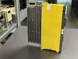
Initial inspection revealed no external mechanical damage, but noticeable contamination around the heatsink and airflow paths. The cooling fan already showed increased operating noise, indicating prolonged thermal stress.
Electrical pre-testing without motor connection confirmed that alarm 8 occurred immediately after power-on. This behavior strongly indicates an internal overcurrent condition rather than a motor-related fault. Measurement of the DC bus voltage showed stable values, ruling out external overvoltage.
After opening the unit, thorough cleaning and detailed diagnostics were performed. Uneven thermal discoloration was observed in the power stage area, indicating long-term overload or asymmetric current flow. The control board showed no visible burn marks, but aging effects were evident in the current sensing area.
During the repair process, all thermally and electrically stressed assemblies were carefully inspected. The power stage was removed, measured and preventively refurbished. In parallel, the precharge circuit was checked, as improper precharge behavior frequently leads to secondary current-related faults.
Following reassembly, the unit was tested on a dedicated test bench. The DC bus charged smoothly, the precharge sequence completed within specification and no alarms occurred. A multi-hour load test with cyclic current demand was then performed to simulate thermal stress conditions.
The module passed all tests without recurrence of the fault. After final documentation and sealing, the unit was prepared for return shipment.
Preventive Measures for the Customer
• Regular cleaning of heatsinks and air channels
• Preventive replacement of aging cooling fans
• Monitoring of supply voltage quality
• Avoid frequent power cycling
• Periodic inspection for thermal discoloration
Conclusion
Alarm code 8 on Fanuc servo amplifiers is a serious indication of internal overcurrent conditions. Structured diagnosis and professional repair prevent secondary damage to motors and CNC systems. Preventive maintenance significantly extends the service life of these drive units and reduces unplanned machine downtime.
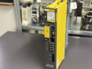
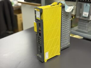
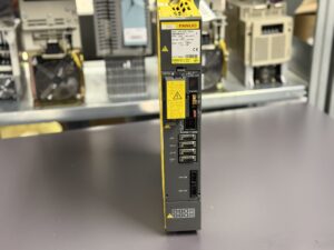
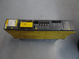
To mentioned Fanuc Drive: Fanuc A06B-6096-H116 Servo Drive Unit
More details about our Fanuc repair services can be found here:
Fanuc drive Repair by Industrypart
📞 Feel free to contact us with any questions about your Fanuc drive technology.
Our expert team is happy to help!
Device Description
| Parameter | Value |
|---|
| Manufacturer | FANUC LTD |
| Type | Servo Amplifier Module |
| Model | A06B-6096-H116 |
| Series | Fanuc Servo Amplifier SVY |
| Supply Voltage | 283–325 V DC bus |
| Rated Power | approx. 7.5 kW |
| Maximum Output Voltage | 230 V AC |
| Rated Output Current | approx. 35 A |
| Axis | L-axis |
| Cooling | Convection cooling via heatsink |
| Mounting | Control cabinet |
| Display | 7-segment LED |
| Certification | CE |
| Manual Reference | Fanuc Servo Maintenance Manual Series 15 |
Operating Environment and Compatible Devices
The Fanuc A06B-6096-H116 Servo Drive Unit is typically used in CNC machine tools such as machining centers, lathes and special-purpose machines equipped with Fanuc Series 15 control systems.
The module operates with Fanuc AC servo motors of the corresponding power class and is designed for continuous industrial operation. Typical environments include production halls with elevated dust levels, fluctuating ambient temperatures and high electrical stress caused by frequent acceleration cycles.
Functional Description
The servo amplifier converts the DC bus voltage into a precisely controlled three-phase AC voltage for driving the servo motor.
Current and speed control are integrated, along with comprehensive protection functions against overcurrent, overvoltage, undervoltage, overheating and internal faults.
The internal precharge circuit ensures safe charging of the DC link capacitors, while continuous monitoring of the power stage guarantees reliable operation. Faults are displayed numerically via the 7-segment LED and can be clearly assigned using the alarm table.
Alarm Messages and Troubleshooting
| Code | Description | Cause | Remedy |
|---|
| 8 | Abnormal current alarm | Overcurrent in power stage | Check power module and motor wiring |
| 9 | IPM alarm | Fault in intelligent power module | Inspect and repair power stage |
| SV004 | DC link overvoltage | Excess regeneration or regulation fault | Check braking circuit |
| SV005 | Precharge alarm | Precharge incomplete | Inspect precharge circuit |
| SV006 | Control power undervoltage | Control supply failure | Check power supply |
| SV023 | Fan stop alarm | Cooling fan failure | Replace fan |
| SV110 | Alpha pulse coder error | Encoder fault | Check encoder and cable |
| SV114 | Rotation speed data error | Feedback inconsistency | Verify parameters |
| SV115 | Pulse coder communication error | Communication fault | Inspect wiring |
| SV117 | Current conversion error | Current measurement fault | Check measuring circuit |
Main Components
| Assembly | Description | Function | Notes |
|---|
| Power module | IPM unit | Motor current generation | Thermally critical |
| Control board | Control PCB | Regulation and monitoring | Sensitive to voltage stress |
| DC link capacitors | Intermediate circuit | Energy storage | Subject to aging |
| Precharge resistor | Precharge circuit | Soft DC charging | Common failure point |
| Heatsink | Cooling element | Heat dissipation | Cleanliness required |
| Fan | Cooling fan | Temperature control | Wear part |