06.03.2026 by Viktor Siebert
Repair of a Yaskawa SGDH-20AE Servopack with intermittent shutdowns and alarms A.40, A.41 and A.10
Initial Situation and Observed Fault.
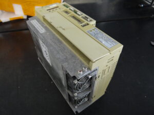
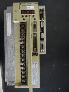
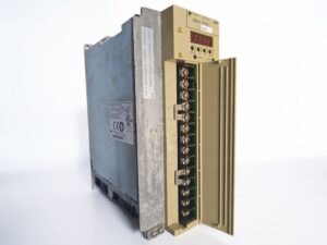
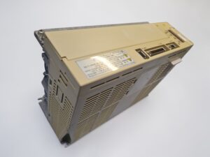
A Yaskawa SGDH-20AE AC Servopack was received for repair due to intermittent shutdowns during machine operation. The customer reported that the servo drive stopped randomly and then restarted after resetting the alarm.
The failure occurred under different operating conditions. Sometimes the drive ran for long periods without problems, while in other cases it shut down shortly after startup.
During the faults the drive displayed different alarm codes. The most commonly reported alarms were A.41, A.40 and occasionally A.10.
Initially the machine operator suspected mechanical vibration inside the control cabinet. Later the suspicion shifted toward overheating of the drive. Both assumptions were partially confirmed during the diagnostic process.
What made this case technically interesting was that the alarm codes were not consistent. Multiple different protection functions were triggered, which is often an indicator of unstable internal conditions or thermally induced intermittent faults.
Incoming Inspection and First Diagnosis
After arrival at the workshop the drive underwent the standard incoming inspection procedure.
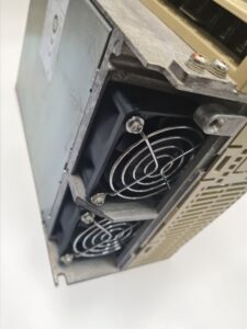
During visual inspection heavy contamination was found in the cooling section of the drive. The internal cooling fans were heavily clogged with dust and debris. Airflow through the cooling channels and heat sink was therefore significantly restricted.
The unit was powered on at the test bench to reproduce the problem. After some operating time intermittent shutdown behavior could be reproduced.
At the same time thermal measurements were performed. These measurements showed that the internal temperature of the power stage increased unusually quickly.
This observation strongly indicated a cooling problem affecting the power electronics.
Technical Analysis
After disassembling the drive the power stage was inspected in detail.
Due to the blocked cooling fans the internal temperature of the drive had been elevated for an extended period. Continuous thermal stress affected both power electronics and surrounding circuitry.
Several components in the power stage showed signs of thermal aging. Some SMD components had partially lifted from their solder pads due to repeated thermal expansion cycles.
This type of damage commonly causes intermittent electrical contact.
The technical cause-effect chain can be summarized as follows:
Contaminated cooling system → restricted airflow → elevated internal temperature → thermal expansion stress → damaged solder joints → intermittent electrical contact → protective shutdown.
Because multiple circuits were affected, the drive produced different alarm codes during operation.
Protection functions such as overcurrent monitoring, DC bus voltage supervision and thermal protection responded at different moments depending on the internal conditions.
These protective mechanisms are designed to stop the drive immediately in order to prevent damage to the motor, machine or power electronics.
Repair and Refurbishment
The repair process began with a complete disassembly of the Servopack.
All cooling channels, fans and heat sinks were thoroughly cleaned to restore proper airflow. The cooling fans were replaced because their bearings had been exposed to long-term contamination and heat.
The power stage was then inspected and refurbished. Thermally stressed components were replaced and affected solder joints were stabilized.
Several preventive actions were also carried out during the repair.
All internal connectors were cleaned and inspected. The thermal interface between power components and heat sink was checked and restored where necessary. The drive was then reassembled and prepared for testing.
Final Functional Test
After the repair the Servopack was tested on a dedicated servo drive test bench.
The test environment simulated a typical machine installation with a three-phase supply voltage of approximately 200 to 230 volts and a simulated motor load.
The test procedure included the following operating states:
Power-on behavior
Reference operation
Low-speed operation
Medium-speed operation
High-speed operation
Additional tests were performed to monitor current signals, temperature stability and protection functions.
During extended continuous operation the internal temperature remained stable and no alarm messages occurred.
The drive operated reliably across the entire speed range and the original fault could no longer be reproduced.
Conclusion
The root cause of the failure was a combination of blocked cooling fans and long-term thermal stress inside the power stage.
The restricted airflow caused increased internal temperatures during operation. Over time this thermal load damaged solder joints and caused intermittent electrical contact.
By restoring the cooling system, replacing the fans and refurbishing the power stage, the drive could be returned to stable operation.
Regular maintenance of cooling systems inside control cabinets can prevent such failures and significantly extend the service life of servo drives.
Further information such as price and delivery time for:
Yaskawa Servopack SGDH-20AE
More details about our Yaskawa repair expertise can be found here: Yaskawa SIGMA II repairs by Industrypart
Similar models we regularly repair:
SGDH-20AE-OY
SGDH-20DE (400 Volt)
Technical Specifications
| Parameter | Value |
|---|
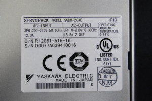
| Manufacturer | Yaskawa Electric |
| Device type | AC Servo Drive Servopack |
| Model | SGDH-20AE |
| Series | Sigma II |
| Rated power | approx. 2.0 kW |
| Input voltage | 3-phase 200 to 230 V |
| Output voltage | 3-phase 0 to 230 V |
| Output frequency | 0 to approx. 300 Hz |
| Rated current | approx. 18.5 A |
| Control method | Vector control with encoder feedback |
| Cooling | Forced air cooling with fan |
| Protection rating | IP1X |
| Ambient temperature | approx. 0 to 55 °C |
| Mounting | Control cabinet mounting |
| Country of origin | Japan |
| Product status | discontinued |
Operating Environment and Typical Applications
The SGDH series servo drives are widely used in CNC machines, machining centers, robotics systems and automated production equipment.
Typical production years for this series range from the late 1990s to the mid-2000s.
In these systems the Servopack controls high-performance servo motors responsible for axis positioning and motion control.
The drive operates in a closed-loop control system using encoder feedback for precise speed and position regulation.
Installation normally takes place inside industrial control cabinets. Reliable operation requires stable electrical supply, proper ventilation and a clean environment.
Functional Description
A servo drive such as the SGDH-20AE supplies controlled power to a servo motor and manages its motion behavior.
The drive converts the three-phase input power into a variable output for the servo motor. At the same time the internal controller processes feedback signals from the motor encoder.
The control structure includes multiple control loops:
Current control loop
Speed control loop
Position control loop
In addition to motion control the drive continuously monitors several protective conditions.
These include temperature monitoring, overcurrent detection, DC bus voltage supervision and internal signal diagnostics.
If an abnormal condition occurs the drive immediately disables the motor output and displays an alarm code in order to protect the system.
Alarm Codes and Troubleshooting
| Alarm Code | Description | Possible Cause | Recommended Action |
|---|
| A.10 | Overcurrent or heat sink overheating | Power stage overload, blocked cooling fan, short circuit, thermal damage | Check power stage, verify cooling system, inspect motor wiring |
| A.40 | Overvoltage | Excessive DC bus voltage, regeneration energy, high supply voltage | Check input voltage and braking conditions |
| A.41 | Undervoltage | Low DC bus voltage, voltage drop, unstable power supply | Inspect power supply and wiring |
| A.30 | Regeneration error | Regeneration circuit malfunction | Check regeneration circuit |
| A.32 | Regenerative overload | Excessive braking energy | Check load inertia and deceleration settings |
| A.33 | Main circuit wiring error | Incorrect power supply wiring | Inspect wiring |
| A.51 | Overspeed | Motor speed exceeded allowed value | Check feedback and parameters |
| A.71 | Overload high load | Short-term overload | Inspect mechanical load |
| A.72 | Overload low load | Long-term overload | Check operating conditions |
| A.7A | Heat sink overheat | Insufficient cooling | Clean cooling system and inspect airflow |
Main Assemblies
| Assembly | Functional Name | Function | Inspection Notes |
|---|
| Power supply section | Rectifier and DC bus | Converts AC supply to DC intermediate voltage | Check DC bus voltage and capacitors |
| Power stage | Motor inverter stage | Generates controlled motor currents | Inspect for thermal stress |
| Control board | Control electronics | Processes feedback and control signals | Sensitive to heat |
| Encoder interface | Feedback processing | Receives position signals from motor encoder | Verify signal integrity |
| Cooling system | Fans and heat sink | Dissipates heat from power stage | Clean regularly and check airflow |