13.10.2025 by Viktor Siebert
Repair of a Yaskawa CIMR-MR5N2015 Converter
Entry and Initial Assessment.
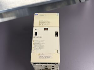
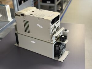
Sometimes a device arrives that, at first glance, doesn’t look like it could still function. But as soon as you open it, you see how much improvisation and necessity are part of industrial processes. The Yaskawa converter CIMR-MR5N2015 that came to us from Norway was exactly that kind of case.
The customer gave us a short but very precise error description:
“When I run up the spindle slowly, it works. If I speed it up fast, it fails.”
A sentence that says a lot when you read it the right way. In practice, this means: the current flow in the power stage is unstable at low rpm still within tolerances, at fast acceleration it exceeds the limits of the IGBTs. That suggests a thermal or structural damage in the power stage.
Visual Inspection and First Findings
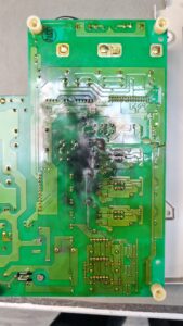
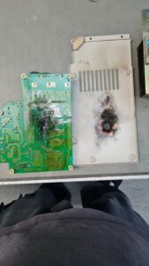
Already when unpacking, we noticed the typical smell: slightly sweet, burnt an unmistakable sign that something inside had overheated. When we opened it, the suspicion was confirmed. The transistor module, the heart of the power stage, was partially burned. The control board above it showed clear discolorations and carbonization, especially in areas where the heat had accumulated. Despite these serious damages, the device according to the customer, had been running for months. He had no choice, a critical job, ongoing production, no spare device available. A scenario we know all too well in industry.
Risks from Thermal Damage
What many don’t realize: continuing operation under these conditions is an enormous risk. The converter could have short-circuited at any moment not quietly, but with a loud bang, smoke, flames, and a large arc fault. The adjacent PCBs and cable assemblies would also have been affected. Fortunately, that didn’t happen. But the signs were evident: the solder mask on the control board was blistered in several spots, the copper traces slightly charred, and the IGBT body underneath showed black inclusions.
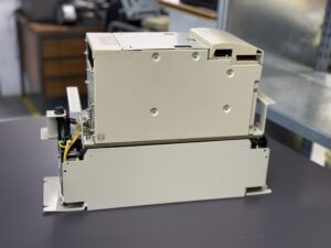
Disassembly and Root-Cause Analysis
We decided to fully disassemble the unit. Every screw, every component was individually inspected, cleaned, and documented. The burnt transistor module was removed, its terminals had practically fused. Such damage often arises when there are long-term contact resistances, e.g. due to loose screws, material fatigue or fine cracks in solder joints. The electric current generates heat, which in turn worsens the contact further, a creeping vicious circle.
The control board above it was still functionally intact on the surface, but the discolorations allowed no peace of mind. We conducted a thermal stress analysis: Several zones had reached temperatures above 100 °C values that drastically shorten the lifespan of PCBs and components. The risk of later failure was simply too high. So we decided to replace that board completely, even though it initially “still worked.” That is a point where experience and responsibility show: just because a component still functions doesn’t mean it’s safe.
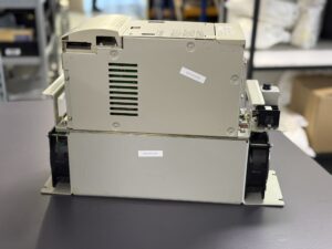
Cleaning and Reassembly
In parallel, the unit was thoroughly cleaned. All soot, dust, and old thermal compound residues were removed. The heat sinks were planed and refilled with fresh thermal interface material to ensure ideal heat conduction. The DC-link capacitors were tested, insulation values measured, and the gate driver circuits of the new transistor module were re-calibrated.
This part of the work may seem inconspicuous, but it is decisive: only through meticulous cleaning and restoration of thermal interfaces can a unit run reliably later. Especially for converters like the CIMR-MR5N2015, which operate under high continuous load, such details determine the lifetime.
Test Run and Measurement Results
For the final functional test, the converter went to our Yaskawa test bench designed for such high-performance devices. Here voltage, current, temperature, and signal quality are measured under real load conditions over several hours. On the first commissioning, everything ran stably. After about 30 minutes, the converter was exposed to load peaks, its behavior remained consistently clean. No voltage drops, no current distortion, no thermal anomalies. The new construction performed exactly within the spec range.
During the final measurement, it became clear how important proactive overhaul is. The new transistor module operated at a significantly lower operating temperature, which not only extends its lifespan but also enhances the overall system stability. That confirmed that the decision was correct: not just replacing the failed module, but also substituting the thermally stressed board.
The Human Behind the Machine
What makes this case special is not only the technical aspect, but also the human side. The customer had improvised for weeks because he lacked a quick solution. He knew the risk was there and sought help only when it was nearly too late. This is everyday reality in many operations: production pressure, missing spares, shortage of specialists all factors that lead to running devices you know are dangerous. That’s precisely why specialized repair shops like ours exist. We understand not only the electronics, but also the situation behind them.
Conclusion and Recommendations
After successful repair, cleaning, and testing, the converter was reassembled and prepared for return shipment. We provided the customer with a summary report and maintenance recommendations: periodic checks of fans, cleaning of cooling paths, and a thermal inspection every 12 months to prevent such thermal damages from ever occurring.
This case vividly shows how important the combination of experience, technical methodology, and responsibility is. A transistor module can be replaced trust and operational safety must be earned. For us, this was not an ordinary repair, but a lesson in how narrow the line between function and disaster sometimes is. In the end, there is a working device, a satisfied customer and the assurance that we kept a piece of industry running.
Further information such as price and delivery time for:
Yaskawa CIMR-MR5N2015 Converter
Yaskawa Inverter CIMR-M5N2015
More details about our Yaskawa repair expertise can be found here: Yaskawa Reparatur bei Industrypart
📞 Please feel free to contact us if you have any questions regarding your Omron drive technology. Our experienced team is always available to assist you.
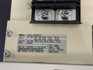
Device Data
Model: Yaskawa CIMR-MR5N2015
Input Voltage: AC 3-Phase 200–220 V 50 Hz / 200–230 V 60 Hz
Input Current: 39.3 A (50 Hz cont.) / 53.6 A (60 Hz 30 min)
Output Voltage: DC 270–325 V
Output Current: 52.4 A cont. / 71.4 A 30 min
Weight: 17 kg
Manufacturer: Yaskawa Electric Corporation (Japan)
Operating Environment & Compatible Devices
The Yaskawa CIMR-MR5N2015 is part of the VARISPEED-626M5 / 656MR5 system, which consists of an Inverter (CIMR-M5) and a Converter (CIMR-MR5).
This system was specifically developed for machine tool spindle drives, designed to deliver high torque density, stable speed control, and regenerative power feedback to the grid.
Typical applications include:
- CNC machining centers with integrated spindle and axis drives
- High-speed spindles for precision metal cutting and hard material processing
- Systems with braking and regenerative operation for improved energy efficiency
Compatible inverter and motor series:
- Spindle Inverters: Yaskawa CIMR-M5A, CIMR-M5N, CIMR-M5D-….
- Spindle Motors: Yaskawa UAASKA-… and UAASKB-… series (Standard and Winding-Selection types, 200 V / 400 V classes)
- Encoders: UTMSI-10AAGAZA, UTMSI-10AAGBZA
- Control environments: Stand-alone Yaskawa systems or customized CNC controllers using analog or digital speed reference signals (e.g. ±10 V or 12-bit digital input)
The overall system forms a closed Yaskawa spindle drive architecture, where the converter and inverter are connected via a DC link.
Regenerative energy from the spindle is fed back through the MR5 converter into the power supply, ensuring high energy efficiency and thermal stability during continuous operation.
Converter Alarm Table (Fault Codes and Corrective Actions)
| Fault No. | Alarm Name | Description | Possible Cause | Corrective Action |
|---|
| 01 | Overcurrent | Output current exceeded detection level | Shorted load, incorrect wiring, overvoltage on input | Check load, wiring, and input voltage |
| 04 | Main Circuit Fuse Blown | Fuse in main power circuit has opened | Damaged transistor or ground short | Replace damaged components and fuse |
| 05 | Overload | Output current exceeded overload limit | Load too high, improper capacity selection | Reduce load or verify converter sizing |
| 11 | Output Overvoltage | DC bus voltage exceeded limit (approx. 400 V for 200 V class) | Input surge, regenerative voltage from inverter | Check input voltage and motor deceleration |
| 12 | Main Circuit Undervoltage | DC voltage below minimum threshold | Low supply voltage | Check supply voltage and connections |
| 14 | Control Circuit Undervoltage | Control power below threshold | Low or unstable control voltage | Verify control power source |
| 15 | Power Supply Frequency Fault | Supply frequency outside ±5 % of 50/60 Hz | Power instability or phase issue | Check power waveform and line conditions |
| 16 | Initial Charging Fault | DC link capacitors not charged in time | Capacitor aging or rectifier issue | Replace converter or repair charge circuit |
| 17 | Power Supply Open Phase | Missing input phase detected | Faulty wiring or fuse | Check phase connection and input lines |
| 23 | Built-in MC Operation Fault | Magnetic contactor failed to operate | Coil or driver failure | Replace magnetic contactor or unit |
| 43 | Heatsink Overheat 1 | Temperature exceeded upper warning limit | Blocked air path or fan slowdown | Clean cooling ducts, check fan |
| 44 | Heatsink Overheat 2 | Temperature exceeded for more than 1 min | Cooling failure | Verify ventilation and ambient temperature |
| 45 | Heatsink Thermistor Disconnection | Sensor disconnected or faulty | Damaged thermistor or wiring | Replace thermistor or repair wiring |
| 46 | Control PCB Overtemperature 1 | Control board > 80 °C | Inadequate airflow | Improve cooling and environment |
| 47 | Control PCB Overtemperature 2 | Control board > 85 °C | Prolonged heat exposure | Ensure ventilation, clean interior |
| 50 | CPU / A-D Converter Error | Internal CPU or ADC fault | Control board failure | Replace control PCB |
| 52 | EEPROM / ROM Error | Memory read/write fault | Aging or corrupted memory | Replace control PCB |
| 53 | WDT Time Exceeded | Watchdog timer error | Software or hardware lock-up | Restart, if repeated replace control PCB |
Components (Main Internal Parts)
| Section | Description / Part Name | Board Code / Model | Function | Notes |
|---|
| Control Board | Main Control PCB | YPHT31149-xD | Controls converter logic, protection, and communication with inverter | Mounted on top of power section |
| Power Board | IGBT Power PCB | YPCT31244-1B / ETC626095 | Drives IGBT transistors, manages power stage switching | Thermally sensitive component |
| Power Module | Transistor / IGBT Module | – | Converts AC input to DC output via rectification and switching | Subject to thermal load |
| DC Link Capacitors | Electrolytic Capacitors | – | Stabilize DC bus voltage and filter ripple | Periodic inspection recommended |
| Heatsink Assembly | Cooling System | – | Transfers heat from power stage to air flow | Requires functional fan and clean surface |
| Connector Interface | 1CN / 5CN / 51CN / 52CN | – | Signal and power interface to inverter and control circuits | Ensure firm seating and clean contacts |
| Fan Unit | Cooling Fan | – | Ensures forced air cooling for IGBT and control section | Replace every 2 years or 6000 h |