28.02.2026 by Viktor Siebert
Repair of a Yaskawa Servopack CACR-SR30SB1BFY100 with overcurrent alarm A.1 due to faulty current measurement and worn power stage
Initial situation and fault description
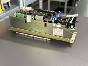
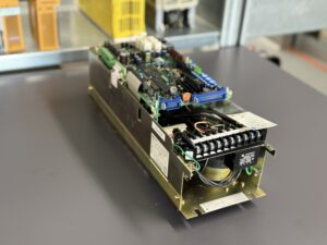
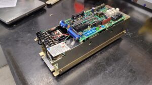
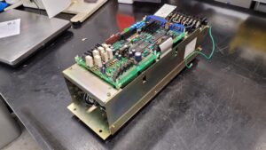
A Yaskawa Servopack CACR-SR30SB1BFY100 was sent in for repair. The unit belongs to the proven CACR-SR series, often referred to as VS-800, and is typically used in older CNC machines. The SR30 power class corresponds to approx. 3.0 kW.
According to the technician’s report, the connected motor started briefly during testing, vibrated noticeably and then shut down with alarm A.1. The fault occurred reproducibly during acceleration. In idle condition, no abnormality was visible.
Technically striking was the strong vibration immediately after the enable signal, followed by a rapid shutdown. This behavior indicates an inconsistent current feedback, where the internal overcurrent monitoring responds although there is no mechanical blockage.
Incoming inspection and initial diagnosis
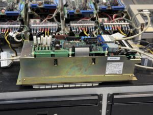
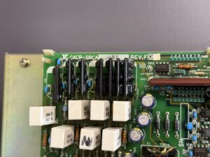
After arrival, a standard visual inspection was carried out. The unit showed age related thermal traces in the power section area. Connectors and terminals were mechanically intact. No obvious broken traces or burn marks.
For the first functional test, the servopack was connected to a test bench with three phase supply approx. 3 x 230 V AC. Before opening the unit or disconnecting connectors, it was disconnected from power, secured against reconnection, the discharge time of the DC link capacitors was observed and absence of voltage was verified.
During the start attempt with reference signal, the motor started briefly but showed clear torque oscillation. Within a few hundred milliseconds, fault A.1 appeared, which in this series indicates an overcurrent condition. Shutdown was performed dynamically via the internal protection logic.
Initial measurements showed that the output currents were asymmetrical and not plausible relative to the load. The current indication in the green measuring circuit deviated significantly from the actual phase current measured with an oscilloscope.
Technical analysis
The CACR-SR series operates with a hybrid analog and digital control structure. Current control is based on internal phase current measurement used as the control variable for pulse width modulation. If a limit value is exceeded or appears to be exceeded, protection function A.1 is triggered.
In this case, the internal current sensor delivered incorrect measured values. The cause was a known weak point of this series in the current sensing section. Due to aging and thermal stress, measurement characteristics drift. The result is incorrect feedback to the current control loop.
Cause effect chain:
Aging of the current sensing component leads to distorted current feedback.
The control interprets this as overcurrent.
The protection logic triggers alarm A.1.
The motor is dynamically shut down.
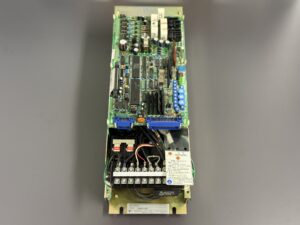
Additionally, the power stage showed clear signs of wear. The drive stages of the power section exhibited thermal pre damage. Isolated signal drivers in the control section were also affected. This led to unstable pulse modulation, further intensifying the vibration behavior.
This combination of faulty current measurement and worn power stage explains the observed startup behavior.
Repair measures and refurbishment
The repair was carried out in several steps.
First, the complete power stage was overhauled. Heavily stressed power modules were replaced. The control boards with isolated signal transmission were fully renewed.
The faulty current sensor was replaced by a revised version. Afterwards, the current feedback was calibrated to nominal current approx. 26 A according to the SR30 power class.
In addition, the following preventive measures were performed:
• Replacement of thermally stressed heatsink connections
• Cleaning of cooling channels and fan unit
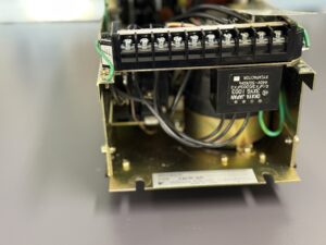
• Inspection of connectors 1CN and 2CN
• Verification of encoder signal quality
• Checking DC link capacitors for ESR and capacitance
All work on live components was carried out exclusively by qualified electrical personnel using appropriate measuring equipment and in compliance with applicable safety regulations.
Final functional test
The functional test was performed on the in house test bench.
Supply: 3 x 230 V AC
Motor load: simulated nominal load approx. 3 kW
Speed range: 0 to 2000 rpm
Test procedure:
• Multiple on off cycles tested
• Reference run at low speed approx. 100 rpm
• Medium speed approx. 1000 rpm
• High speed near nominal speed
• Load changes under continuous operation
• Overcurrent protection test
• Thermal monitoring over approx. 120 minutes
The motor started smoothly without vibration. No renewed A.1 triggering. Current draw was symmetrical and within specification. Temperature behavior was normal.
Result: fault free, stable, reproducible.
Conclusion
Alarm A.1 was caused by distorted current feedback combined with a worn power stage. After replacement of the affected assemblies and recalibration, the servopack operates again within specification.
The repair is sustainable because thermally stressed components were also replaced preventively. This significantly increases operational reliability and avoids unplanned downtime.
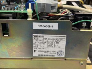


To mentioned Yaskawa Drive: Yaskawa CACR-SR30SB1BFY100 AC Servopack
More details about our Yaskawa repair services can be found here:
Yaskawa drive Repair by Industrypart
📞 Feel free to contact us with any questions about your Yaskawa drive technology.
Our expert team is happy to help!
Technical Specifications
| Parameter | Value |
|---|
| Manufacturer | Yaskawa |
| Device type | Servo Drive |
| Model designation | CACR-SR30SB1BFY100 |
| Series | CACR-SR |
| Power | approx. 3.0 kW |
| Input voltage | 3 x 200 to 230 V AC |
| Output voltage | 3 x 0 to approx. 230 V AC PWM |
| Rated current | approx. 26 A |
| Control type | Analog speed control |
| Feedback | Incremental encoder 5000 P/R |
| Cooling | Integrated fan |
| Protection class | IP20 |
| Ambient temperature | 0 to 55 °C |
| Mounting | Control cabinet mounting |
| Origin | Japan |
| Product status | Discontinued |
Operating environment and application
Typical applications are CNC lathes, milling machines and machine tools from the 1980s and 1990s. Often combined with Yaskawa AC servo motors of the M or F series.
The drive is suitable for positioning tasks with analog reference input. The control cabinet environment should be well ventilated. High continuous thermal stress accelerates aging of power components.
Regular inspection of fan operation and DC link voltage is recommended for older systems.
Functional description
The servopack converts the three phase mains voltage into a controlled PWM output voltage for the servo motor. The internal current control is based on measurement of the motor phase current.
Power stage, control and feedback operate in a closed loop. The encoder provides position and speed information. Current feedback protects against overload.
Protection functions include overcurrent, overvoltage, overheating and phase loss. If limit values are exceeded, dynamic shutdown occurs.
These protection mechanisms are safety relevant as they protect power semiconductors and motor from destruction.
Alarm Messages and Troubleshooting
| Code | Fault description | Cause | Solution |
|---|
| A.1 | Overcurrent | Motor short circuit or faulty current measurement | Check motor, inspect current sensing |
| 1 | Overcurrent | Phase short circuit | Check wiring |
| 2 | Main circuit fuse | Internal short circuit | Inspect power section |
| 3 | Regeneration error | Braking resistor defective | Check resistor |
| 4 | Overvoltage | Mains voltage too high | Check mains supply |
| 5 | Overspeed | Encoder signal faulty | Check encoder |
| A | Overload | Mechanical blockage | Check load |
| B | Heatsink overheat | Fan defective | Check fan |
| F | Phase loss | Missing phase | Check mains |
| 8 | Cooling fault | Insufficient air circulation | Check control cabinet |
Assembly Overview
| Assembly | Functional designation | Function | Inspection or repair notes |
|---|
| Power stage | Power section | Motor drive output | Check for thermal stress |
| Current sensing | Current measurement circuit | Feedback for control loop | Calibrate |
| Gate drive stage | Drive stage | Switching of power modules | Check signal waveform |
| DC link | DC bus | Energy buffering | Check capacitance and ESR |
| Fan unit | Cooling | Heat dissipation | Check rotation speed |
| Control board | Control electronics | Setpoint actual comparison | Visual inspection |