22.02.2026 by Viktor Siebert
Repair of a Yaskawa spindle system UAASKA-06FZ1N with UTMSI-10AAGAZA encoder and VS-626M5 CIMR-M5A27P50-XXXC inverter: Low speed positioning failure caused by contamination related encoder damage
Initial situation and fault pattern.
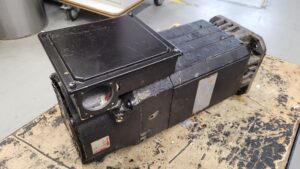
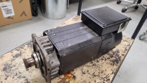
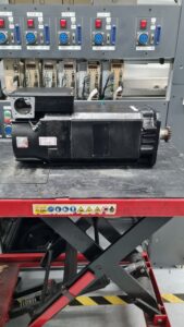
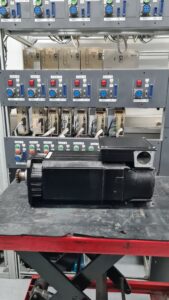
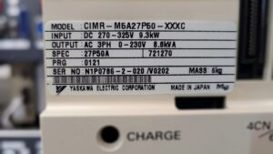
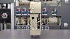
Delivered was a spindle drive consisting of a Yaskawa AC spindle motor UAASKA-06FZ1N with encoder UTMSI-10AAGAZA, operated on a Yaskawa inverter VS-626M5 (CIMR-M5A27P50-XXXC). The customer reported that the motor does not regulate cleanly and cannot be positioned reliably at low speeds. The correlation with operating actions such as spindle orientation for tool changes or slow positioning moves was noticeable. In mid speed ranges, a start was partly possible, but during deceleration and in the lower speed band there were jerking, speed fluctuations, and sporadic aborts by the drive.
Technically, this behavior is typical for a disturbed encoder feedback, because in closed loop control the feedback signals are the basis for speed stability and orientation. Especially at low speeds, even a short implausibility of the pulses leads to significant control deviations.
Incoming inspection and first diagnosis
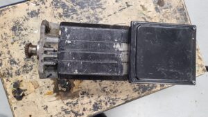
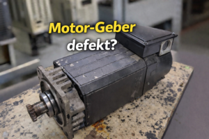
During the visual inspection, contamination was visible in the area of the encoder sealing as well as deposits that occur in machining environments due to chips, dust, and coolant mist. No mechanical damage was visible on the motor housing or on the power connections.
On the test bench the fault could be reproduced. With low speed setpoints and during orientation, the control loop reacted unsteadily, and the speed display showed jumps that do not match the mechanical inertia. Insulation measurement and phase comparison of the motor winding were inconspicuous. Checking the encoder supply and the feedback signals, however, showed sporadic dropouts at slow rotation. This placed the first narrowing down in the functional area of feedback, signal quality, and mechanical encoder coupling.
Technical analysis
The encoder provides the pulse train for actual value generation and the index information for orientation. At low speeds the pulse density is low, so missing, deformed, or jittering signals become visible immediately as actual value jumps. The inverter compensates these supposed deviations with torque corrections, which appears as jerking and missing positioning accuracy. During orientation, implausible index information leads directly to position errors or an abort.
The inspection of the encoder area confirmed the root cause. Ingressed dirt reduced the required clearance in the encoder area. During operation this led to friction contact between the rotating encoder disk and the sensor unit. The progressive abrasion destroyed the sensing unit, making the feedback signals unreliable especially in the lower speed range. The damage pattern matches a gradual development under continuous exposure, not a single event.
Repair measures and refurbishment
Because the sensor unit was mechanically damaged, cleaning or adjustment alone was not effective. The repair was therefore carried out by completely replacing the encoder UTMSI-10AAGAZA. In addition, the encoder space, sealing surfaces, and cable feedthrough were cleaned, checked, and rebuilt in a way that reduces renewed dirt ingress. The encoder supply and feedback signals were electrically verified, and the parameterization for encoder operation and orientation on the VS-626M5 was verified.
Final functional test
The functional test was performed on the test bench with the VS-626M5 CIMR-M5A27P50-XXXC and the refurbished motor. Tested were power on and power off behavior, enable sequence, acceleration, deceleration, and stable operation at very low speeds. Orientation and positioning functions were repeated multiple times. The spindle could be aligned reproducibly, and the speed remained stable without jumps or control ripple. Under load changes there were no feedback faults and no protective shutdowns.
Conclusion
The disturbance was caused by a destroyed feedback unit. Contamination in the encoder area led to friction contact and abrasion, causing the control loop to leave the tolerance range especially at low speeds and during orientation. The complete encoder replacement combined with cleaning and a preventive rebuild restores operational safety and addresses the cause of the gradual damage.
Further information such as price and delivery time for the: Yaskawa AC Spindle Motor UAASKA-06FZ1N
More details about our Yaskawa repair expertise can be found here: Yaskawa Repair at Industrypart
📞 Feel free to contact us if you have any questions regarding your Yaskawa drive technology.
Our team looks forward to your inquiry!
Technical specifications
| Field | Value |
|---|
| Manufacturer | Yaskawa |
| Device type | AC spindle motor |
| Model designation | UAASKA-06FZ1N |
| Series | UAASKA |
| Power | approx. 3.7 kW S1 continuous duty, approx. 5.5 kW short time duty (typical for UAASKA-06 variants) |
| Input voltage | approx. 3 phase 200 V AC class, variable from the spindle inverter (frequency and voltage depend on speed) |
| Output voltage | not applicable, mechanical output |
| Rated current | approx. 29 A S1, approx. 39 A short time (typical for UAASKA-06 variants) |
| Control mode | operation on a spindle inverter, control method depends on inverter and parameterization |
| Feedback | speed and position feedback via encoder UTMSI-10AAGAZA |
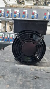
| Cooling | externally fan cooled, depending on installation and airflow |
| Protection rating | approx. IP44 (typical, verify nameplate and installation) |
| Ambient temperature | 0 to +40 °C |
| Mounting | flange mounting, horizontal or vertical installation possible |
| Origin | approx. Japan |
| Product status | legacy, depending on variant no longer available as new equipment |
Reference notes for typical UAASKA 06 power, current and speed data can be found for comparable UAASKA 06 variants.
Typical protection rating, cooling principle, temperature range and the encoder type UTMSI-10AAGAZA are documented in Yaskawa spindle motor drawings of this design.
Environmental conditions such as 0 to +40 °C and 20 to 80 percent relative humidity as well as the possible installation orientation are stated as typical boundary conditions in Yaskawa motor installation notes.
Product status note: for some UAASKA 06 variants a discontinued status is described in the aftermarket.
Operating environment and application options
Typical machines
- CNC machining centers and milling machines
- CNC lathes
- drilling and grinding applications with speed controlled spindles
Typical production years
- approx. 1990 to 2010, depending on machine builder and retrofit level
Type of applications
- speed control over a wide range with a constant torque range at low speed and a constant power range at high speed
- spindle orientation and positioning functions at standstill or low speed using feedback
Requirements for environment and control cabinet
- clean, dry encoder area, because contamination and abrasion can strongly affect signal quality
- separate, shielded routing of feedback cables and consis
Notes on thermal and electrical stress
- short time overload is possible on system level, but should be limited by parameterization, cooling and load profile
- frequent acceleration and braking cycles increase thermal stress and promote aging of insulation systems and mechanical fits
Functional description
Basic function of the device
The AC spindle motor converts the frequency and voltage variable three phase energy provided by the spindle inverter into torque and speed for the spindle drive.
Interaction of power stage, control, feedback
The spindle inverter generates the speed dependent output frequency and voltage. The control uses encoder feedback to achieve speed stability, spindle orientation and position related functions reliably. Encoder type UTMSI-10AAGAZA is documented as feedback for this design.
Special functions such as enable, protective logic and monitoring
Typical functions include motor thermal monitoring, plausibility checks of feedback signals and protective functions against overcurrent, overload and unstable behavior. These functions prevent consequential damage to spindle mechanics, tooling and workpieces and are therefore safety and process relevant.
Why these functions are safety relevant
Faulty feedback or thermal overload can lead to uncontrolled speed, orientation errors or unplanned stops. In machine tools this can cause damage, scrap or mechanical consequential failures.
Alarm messages and troubleshooting
| Alarm code | Description | Possible cause | Recommended action |
|---|
| A01 | Feedback signal implausible | contamination in encoder area, mechanical damage, interference | inspect encoder area, check cables and shielding, replace encoder if signals remain unstable |
| A02 | Encoder signal missing | open feedback line, defective feedback | check connectors, measure continuity, replace feedback device |
| A03 | Spindle orientation cannot be reached | faulty feedback, unsuitable parameters, mechanical load too high | check feedback and parameters, verify load conditions |
| A04 | Motor overtemperature | insufficient cooling, blocked airflow, overload profile | check airflow and cooling, reduce load profile, test thermal monitoring |
| A05 | Motor overload | continuous load too high, ramps too steep | adjust ramps, check process load, restore thermal margin |
| A06 | Overcurrent at start | parameter mismatch, mechanical blockage, insulation issue | check mechanics, perform insulation test, verify parameters |
| A07 | Ground fault or insulation error | moisture, cable damage, insulation aging | insulation test, check cables, assess motor condition |
| A08 | Overshoot or resonance | mechanical resonance, unfavorable controller settings | optimize controller settings, check mechanical coupling |
| A09 | Speed deviation too large | disturbed feedback, EMC interference, load steps | check shielding and grounding, verify feedback, evaluate load steps |
| A10 | Cooling effectiveness insufficient | ventilation failure, contaminated air paths | clean air paths, check ventilation, evaluate temperature behavior in test run |
Assembly overview
| Assembly | Designation (functional, no part numbers) | Function | Notes for inspection or repair |
|---|
| Power conversion | electromagnetic drive system | generates torque from inverter power | check winding condition via insulation test and symmetry |
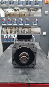
| Mechanical output | shaft and interface to spindle | transfers torque into the machine | check runout, fit surfaces, play and noise |
| Bearing system | shaft support | smooth running and service life at high speed | check noise, temperature, axial and radial play |
| Feedback | encoder unit | speed and position information for control | test signal quality at low speed and orientation, exclude contamination |
| Thermal monitoring | temperature supervision | protection against overheating | verify plausibility during warm up, confirm trip behavior |
| Cooling | external ventilation and airflow path | heat removal from motor | clean air paths, ensure installation and airflow |
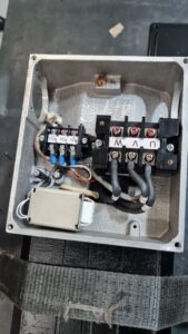
| Connection system | power and feedback connections | safe electrical connection | check contact condition, strain relief, shielding concept |
| Sealing concept | protection against oil and coolant | reduces contamination and moisture | inspect sealing areas, keep encoder area especially clean |