23.04.2026 by Viktor Siebert
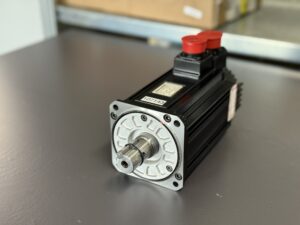
Yaskawa AC Servo Motor SGMSH-20PCA-SB23 with Bearing Damage and Scraping Noise
Initial situation and fault pattern.
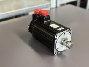
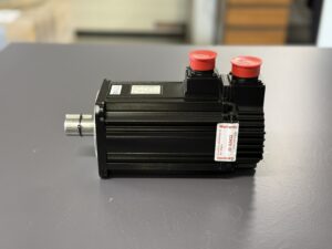
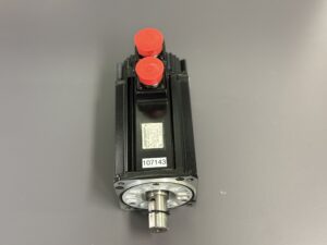
The Yaskawa AC Servo Motor SGMSH-20PCA-SB23 came into our workshop with a clearly mechanically driven fault pattern. It had already been described on arrival that the motor was producing scraping noises. With this motor type, such noises are technically relevant because they can indicate not only advanced bearing damage, but in continued operation can also cause side effects on running behavior, temperature, vibration, and signal quality of the feedback system. In the field, that is often exactly the problem. The drive still runs at first, but is already clearly acoustically abnormal before secondary damage occurs to the shaft, feedback system, or connected power electronics.
In the present case, the motor was tested by us on a Yaskawa SGDH-20AE. This is important for fault isolation because it allows a quick distinction between a pure control problem in the amplifier and a cause that is actually inside the motor itself. With mechanical noises during rotation, the cause is not always clear at first. Possible causes include contact in the feedback area, a problem in the motor brake, foreign particles in the ventilation area, or damaged bearings. Here it was noticeable that the noise was clearly audible during the test run regardless of load and therefore did not indicate a purely machine side connection problem.
Incoming inspection and initial diagnosis
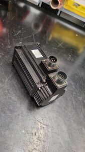
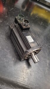
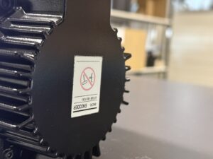
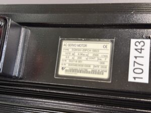
During the incoming inspection, the nameplate was first recorded and the motor was visually inspected. No major housing damage or indications of an acute electrical breakdown were visible. For the initial assessment, three points are decisive in such cases. First, the mechanical running feel by hand. Second, the condition of the connection side and the feedback system. Third, the basic electrical inspection before further disassembly.
Already in the initial mechanical inspection it became apparent that the motor no longer ran cleanly and evenly. The noise pattern did not match normal bearing noise caused by aging, but rather advanced wear with the beginning of scraping. Such findings are critical because a pure bearing problem can quickly develop into a combined fault. If running play and roughness increase, additional vibrations occur. These stress the feedback system, worsen control reproducibility, and at the same time increase the thermal and mechanical stress on the rotor system.
Before opening the unit or disconnecting plugs, the equipment must always be switched off, secured against reconnection, the discharge time must be observed, and absence of voltage must be verified. Measurements on live parts may only be carried out by a qualified electrician with suitable equipment and according to local rules.
Technical analysis
Technically, this servo motor only operates cleanly when mechanical running, the magnetic system, and the feedback system work together stably. The bearing plays a central role here. It guides the shaft precisely, limits radial and axial movement, and keeps the air gap and the signal geometry of the feedback system within tight tolerances. As soon as a bearing wears, roughness initially develops in the running behavior. This is then followed by increased noise, rising vibration, and later often heating and positional instability.
The cause effect chain was typical in this case. Mechanical bearing failure led to rough running and scraping noises. This resulted in increased vibrations and growing mechanical instability of the motor. In operation, this instability can lead to the motor still running, but already being clearly acoustically abnormal, and depending on the application, the feedback stability suffering as well. That is exactly what makes such cases tricky in practice. Electrically, there is often no total failure at first. So the motor can still appear to function, even though the mechanical condition is already clearly outside a permanently acceptable range.
Especially with servo drives, such damage is often underestimated. As long as there is still no clear alarm message at the amplifier, the motor continues to be operated. But this greatly increases the risk of consequential damage. At the latest when scraping noises become audible, it must be assumed that the mechanical guidance is no longer working properly.
Repair measures and overhaul
In the repair process, the motor was completely disassembled and mechanically assessed. The focus was on eliminating the bearing damage and restoring clean, low vibration running behavior. After disassembly, the affected functional areas were cleaned, all mechanically relevant contact surfaces were inspected, and the damaged bearing arrangement was repaired or functionally renewed.
In addition, the feedback system was checked with regard to fastening, fit, and general function, since bearing damage must often not be viewed in isolation. Even if the actual failure here was mechanical, checking electrical and feedback related stability is always part of the process. A motor with renewed bearing arrangement is only sustainably overhauled if running accuracy, signal behavior, and temperature development are also unobjectionable afterward.
As a preventive measure, the motor was not only repaired, but brought into a condition that prevents further consequential damage. This includes in particular complete cleaning, inspection of the connection side, and assessment of the overall condition with regard to further signs of wear. The goal is not only short term smooth running, but a technically reliable condition for renewed use.
Final function test
The final test was carried out on our test bench with a Yaskawa SGDH-20AE. The motor was started under controlled conditions, switched on and off, and observed over various speed ranges. The comparison between low speed, medium speed, and higher speed range was especially important here, because bearing damage often becomes more noticeable acoustically or in terms of vibration in certain ranges.
At low speed, attention was paid to even startup and clean running noise. In the middle range, the focus was on smooth running at stable speed. At higher speed, it was checked whether scraping noises, noticeable heating, or instability in the feedback system would reappear. In addition, the on off behavior was observed, because residual play or mechanical roughness can be identified quickly, especially at that stage.
After the overhaul, the motor again showed a significantly smoother running pattern. The previously described scraping noises were no longer detectable during the test sequence. The running behavior was stable, the signals were unobjectionable, and the behavior over the tested speed range was technically plausible.
Conclusion
The present damage was a classic mechanical wear case with a clear focus on the bearing arrangement. The decisive point was that the motor had not yet completely failed despite the damage and therefore represented a typical practical case in which the fault is initially noticeable only through noise and running behavior. Through complete disassembly, technical repair of the bearing arrangement, and subsequent test bench verification, the motor was sustainably overhauled. This not only eliminated the noise, but also restored the basis for clean operation and stable feedback behavior.

Information about the mentioned Servopack and Servomotor:
More information about our Yaskawa repairs can be found here.
📞 Feel free to contact us if you have any questions regarding your Yaskawa drive tec
Technical Specifications
| Field | Value |
|---|
| Manufacturer | Yaskawa |
| Device type | AC Servo Motor |
| Model designation | SGMSH-20PCA-SB23 |
| Series | Sigma II / SGMSH |
| Power | 1670 W according to nameplate |
| Input voltage | approx. 200 V according to nameplate |
| Output voltage | not applicable for motor |
| Rated current | 6.0 A according to nameplate |
| Control type | Servo operation with external control via servo amplifier |
| Feedback | Encoder Yaskawa UTSIE-B17CK |
| Cooling | Self cooling, housing cooling via surface, approx. according to design |
| Protection class | not identifiable from the nameplate, approx. industrial standard for servo motor of this design |
| Ambient temperature | typically industrial environment, exact value not readable from the nameplate |
| Mounting | Flange mounting |
| Origin | Made in Japan according to nameplate |
| Product status | Existing unit / repair case |
| Rated speed | 2500 rpm according to nameplate |
| Rated torque | 6.36 Nm according to nameplate |
| Insulation class | Ins. F according to nameplate |
| Associated test drive | Yaskawa SGDH-20AE |
Operating environment and possible applications
Typical machines
Machine tools, handling technology, feeding systems, axis drives in machining machines, packaging machines, special purpose machinery
Typical years of manufacture
approx. early to mid 2000s, in the present case nameplate date 05/08
Typical applications
Feed axes, positioning axes, rotary auxiliary axes, drive related control tasks with encoder feedback
Requirements for environment and control cabinet
Clean supply to the servo amplifier, stable grounding, proper shielding of the cables, low moisture, low transmission of vibration from the machine, no permanent ingress of oil mist or coolant into plug connections and feedback system
Notes on thermal and electrical load
Mechanical stiffness, blocked bearings, or increased friction directly lead to higher current demand and additional heating. Unstable supply, faulty grounding, or disturbed encoder communication can also trigger control problems and subsequent alarms at the servo amplifier.
Functional description
Basic function
The servo motor converts the controlled variable specified by the servo amplifier into precise rotary motion. Torque generation, smooth running, and stable feedback of actual values are decisive here.
Interaction of power section, control, and feedback
The SGDH amplifier forms the power section and controls current, speed, and motion behavior. The motor converts the power mechanically. The feedback system supplies position and speed information to the amplifier. Precise operation is only possible if all three levels work together cleanly both mechanically and electrically.
Enable
The amplifier only enables the motor after valid enable and plausible feedback are present. Errors in parameterization, wiring, or encoder communication lead to alarm states.
Protection logic
Typical protection functions in the Sigma II environment are overcurrent, regeneration, overvoltage, undervoltage, overspeed, overload, and encoder communication monitoring.
Thermal monitoring
In addition to electrical load, overload conditions and temperature related limit cases are also monitored. Pre warnings for overload and regeneration are documented.
Signal monitoring
The feedback system is monitored for communication errors, checksum errors, data errors, and implausible operating states.
Why these functions are safety relevant
Because mechanical defects, uncontrolled movement, overspeed, voltage faults, or encoder loss can directly lead to axis faults, consequential damage, and dangerous machine conditions.
Alarm messages and troubleshooting
| Alarmcode | Description | Possible cause | Recommended measure |
|---|
| A.02 | Parameter Breakdown | EEPROM data in the amplifier faulty | Check parameters, eliminate the cause, restart the unit |
| A.03 | Main Circuit Encoder Error | Faulty detection data in the power section | Check power section and internal diagnostics |
| A.04 | Parameter Setting Error | Parameter setting outside permissible range | Correct parameters |
| A.05 | Servomotor and Amplifier Combination Error | Motor and amplifier do not match in terms of capacity | Check combination and assign correctly |
| A.10 | Overcurrent or Heat Sink Overheated | Overcurrent in IGBT or heat sink too hot | Check wiring, load, and cooling |
| A.30 | Regeneration Error Detected | Fault in regeneration circuit or resistor | Check regeneration branch and resistor |
| A.32 | Regenerative Overload | Regeneration energy exceeds resistor capacity | Check braking cycles and sizing |
| A.40 | Overvoltage | DC bus voltage too high | Check mains voltage and operating state |
| A.41 | Undervoltage | DC bus voltage too low | Check supply voltage and incoming power |
| A.51 | Overspeed | Motor speed too high | Check control, load release, and parameters |
| A.71 | Overload High Load | Strong overload for several seconds | Check mechanical load and cycle |
| A.72 | Overload Low Load | Continuous overload above rated range | Check process load and sizing |
| A.73 | Dynamic Brake Overload | Braking energy exceeds brake resistor capacity | Check braking operations and sizing |
| A.74 | Overload of Surge Current Limit Resistor | Mains switched on and off too frequently | Reduce switching frequency |
| A.7A | Heat Sink Overheated | Heat sink overheated | Check ventilation, installation condition, and load |
| A.C9 | Encoder Communications Error | Communication between amplifier and encoder disturbed | Check encoder, cable, and plug connections |
| A.CA | Encoder Parameter Error | Encoder parameters faulty | Check encoder data and compatibility |
| A.Cb | Encoder Echoback Error | Communication content to encoder faulty | Check line and feedback system |
| A.d0 | Position Error Pulse Overflow | Position error exceeds limit value | Check mechanics, control parameters, and load |
| A.F1 | Power Line Open Phase | One supply phase missing | Check mains supply and wiring |
Source of alarm codes: Sigma II Alarm Display Table.
Assembly overview
| Assembly | Functional designation | Function | Notes for testing or repair |
|---|
| Stator and rotor | electromagnetic drive system | Converts electrical power into torque | Check for thermal abnormalities, running marks, and mechanical scraping marks |
| Bearing arrangement | mechanical shaft guidance | Ensures smooth and precise running | Check for running noise, play, roughness, and temperature development |
| Encoder / feedback | position and speed detection | Supplies actual values to the servo amplifier | Check signal stability, plug connections, and fastening |
| Connection side | power and signal connection | Connects the motor electrically to the system and amplifier | Check contact condition, sealing, and damage |
| Housing and flange | mechanical integration | Absorbs forces and couples the motor to the machine | Check seating surfaces, fits, and damage |
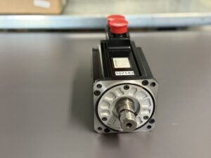
| Shaft | torque output | Transfers motion to the machine | Check for concentricity, fit, and friction marks |
| Insulation system | electrical separation | Prevents leakage and winding faults | Carry out insulation measurement in de energized state |
| Sealing and protective areas | protection against dirt and moisture | Reduces ingress of media and particles | Check condition and prevention during disassembly |