01.03.2026 by Viktor Siebert
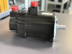
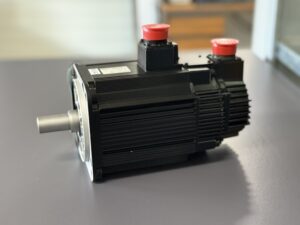
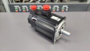
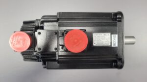
Repair of a Yaskawa AC servo motor SGMGH-13ACA6C with encoder fault due to contamination
Initial situation and fault pattern.
The Yaskawa AC servo motor SGMGH-13ACA6C arrived at the workshop with poor insulation condition and a regularly occurring encoder fault. In the machine, the axis repeatedly aborted during machining. This typically happened after a short runtime or during speed changes. The holding brake, implemented in the system as SBR-112V-200B, was reported by the customer as inconspicuous and this was initially confirmed by its behavior as well.
It was notable that the fault did not appear as a pure start-up fault, but in the middle of the process. In combination with the servo drive SGDH-15AE (Sigma II), an implausible feedback signal leads to the enable being withdrawn and the drive setting alarms in order to stop the axis in a controlled manner.
Incoming inspection and initial diagnosis
Before working on the device, the following applies: switch off the power, secure against being switched on again, wait for the discharge time, and verify absence of voltage. Measurements on live parts may only be carried out by qualified electricians with suitable equipment and according to local rules.
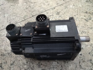
During incoming inspection, the housing, connector areas, and the feedback area were checked. On the test bench, the fault could be reproduced by operating at low speed and observing the feedback. The encoder, in this combination implemented as UTSIH-B17CC, repeatedly showed dropouts. In addition, the insulation condition was checked with the motor disconnected and was initially below the usual expected range.
Technical analysis
The control performance of this motor depends directly on the feedback. The drive compares setpoints with the actual values reported by the encoder. If pulses become incomplete or jumpy, position and speed are no longer plausible, and the drive reacts with an encoder alarm or a feedback fault.
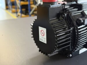
The cause was found to be dirt in the encoder area. Mechanical contact in the encoder chamber created friction that damaged the sensor plane. This caused the feedback signal to become implausible at times. The weak insulation value fits this as well, because contamination and moisture inside the motor housing can increase leakage currents, especially in environments with coolant mist and abrasion.
Repair measures and refurbishment
The motor was cleaned and dried to remove dirt and possible moisture from critical areas. Since the feedback was mechanically damaged, sustainable refurbishment was only possible by completely replacing the encoder. The encoder was replaced as a functionally relevant assembly and rebuilt again as UTSIH-B17CC.
The holding brake SBR-112V-200B was checked. Its switching and holding behavior was inconspicuous, so it remained in the device. In addition, connection areas and plug connections were cleaned and checked from the outside in order to prevent renewed particle ingress into the encoder area.
Final functional test
The functional test was carried out on the test bench with a suitable servo drive and signal monitoring. Tested were positioning at low speed, a speed ramp across a mid range, repeated enable on off behavior, and a longer run for thermal stability. The brake was checked for holding function in a safe state.
The result was stable and fault free. The feedback remained reproducible over the entire test, no encoder alarms occurred anymore, and the motor behaved inconspicuously under the test profiles. This means the combination of motor SGMGH-13ACA6C, encoder UTSIH-B17CC, and brake SBR-112V-200B is suitable again for operation on the SGDH-15AE Sigma II.
Conclusion
The cause was not in the drive itself, but in a mechanically triggered feedback disturbance due to dirt in the encoder area. Friction led to damage of the sensor plane and thus to an implausible feedback signal. Cleaning and drying stabilized the overall condition, the decisive step was replacing the encoder as a complete functional unit. With the test bench run passed at low speed, ramp operation, and thermal load, the repair is traceable and sustainable.
Information about the mentioned Servopack and Servomotor:
More information about our Yaskawa repairs can be found here.
📞 Feel free to contact us if you have any questions regarding your Yaskawa drive technology. Our experienced team is always ready to assist you.
Technical specifications
| Field | Value |
|---|
| Manufacturer | Yaskawa |
| Device type | AC servo motor |
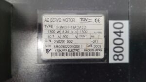
| Model designation | SGMGH-13ACA6C |
| Series | AC Servo Motor (Sigma II system environment) |
| Power | 1300 W |
| Input voltage | 200 V AC, 3 phase, from the servo amplifier |
| Output voltage | not applicable (motor) |
| Rated current | 10.7 A |
| Control type | Sinusoidal servo control via servo amplifier, current and speed control |
| Feedback | Incremental encoder, system dependent, approx. 2048 pulses per revolution |
| Cooling | Self cooling via housing, natural convection |
| Protection class | approx. IP65, depending on shaft seal and connector condition |
| Ambient temperature | approx. 0 to 40 °C |
| Mounting | Flange mounting, axis drive |
| Origin | Japan |
| Product status | presumably discontinued (approx.), legacy spare parts support |
| Rated torque | 8.34 N·m |
| Rated speed | 1500 r/min |
| Duty type | Continuous duty (CONT.) |
| Insulation class | F |
| Holding brake | present, rated voltage system dependent, approx. 200 V DC |
Operating environment and possible applications
• Typical machines: CNC machine tools, handling axes, rotary tables, packaging machines, special purpose machines.
• Typical years in the field: approx. 2000 to 2010, depending on machine series and retrofit.
• Typical applications: positioning, feed axes, cycle operation with frequent acceleration and deceleration.
• Requirements for environment and control cabinet: clean cable routing, sufficient shielding, separate routing of power and feedback lines, functional control cabinet cooling, filter and fan maintenance.
• Notes on thermal and electrical load: continuous operation close to rated current requires stable cooling. Frequent overload peaks are permissible, but increase temperature and aging. Low insulation or moisture in the motor area is a shutdown criterion.
Functional description
The servo motor converts the regulated three phase currents provided by the servo amplifier into torque. Control is performed in the interaction of the power stage in the servo amplifier, control algorithms and feedback on the motor. The feedback supplies position and speed information as actual values. From this arise current control, speed control and position control in a closed loop.
Enable is only given if feedback, temperature monitoring and electrical limits are plausible. Protective functions such as overcurrent, overtemperature, feedback fault and insulation monitoring lead to stop and alarm in the servo amplifier. These functions are safety relevant because they prevent uncontrolled movement, thermal damage and electrical hazards. A holding brake additionally secures standstill, but does not replace correct feedback.
Alarm messages and troubleshooting
| Alarm code | Description | Possible cause | Recommended action |
|---|
| FBK01 | Implausible feedback signal | Contamination or mechanical damage in the feedback area | Stop the machine, save alarm history, have feedback checked properly, replace feedback unit if required |
| FBK02 | Missing pulses or signal interruption | Cable kinked, connector loose, shielding disturbed | Check connectors from the outside, check cable routing, measurement only by qualified electrician, repair cable or feedback |
| FBK03 | Encoder communication disturbed | Disturbances due to proximity to power cables, poor grounding | Route feedback line separately, check shielding concept, check grounding |
| POS01 | Position deviation too large | Feedback faulty, mechanics blocked, parameters implausible | Check mechanics, check feedback, check parameters and load profile |
| OVC01 | Overcurrent | Short circuit, incorrect wiring, mechanical jamming | Stop the machine, check wiring and mechanics, measurements only by qualified electrician |
| TMP01 | Motor overtemperature | Continuous overload, poor cooling, high ambient temperature | Reduce load, improve cooling, check control cabinet temperature |
| ISO01 | Insulation fault or ground fault suspected | Moisture, contamination, damaged cable | Disconnect motor from drive, insulation test by qualified electrician, dry and eliminate the cause |
| OVS01 | Overspeed detected | Feedback faulty, incorrect parameterization | Check feedback, check parameters, check commissioning |
| BRK01 | Brake does not release or does not hold | Brake supply missing, mechanical wear | Check supply and control only by qualified electrician, functionally test brake |
| PWR01 | Undervoltage or supply dip | Mains problem, contactor, supply in the control cabinet | Check mains and contactor only by qualified electrician, check power quality |
| VIB01 | Rough running or hunting | Feedback noisy, resonance, control parameters | Check cable routing and shielding, check parameters, investigate mechanics for resonance |
| ENV01 | Moisture or contamination detected | Coolant, chips, unsuitable installation position | Improve environment, check sealing surfaces, adjust maintenance intervals |
Assembly overview
| Assembly | Functional designation | Function | Notes on testing or repair |
|---|
| Motor body | Electromagnetic converter | Generates torque from regulated three phase power | Visual inspection, odor, thermal traces, resistance measurement by qualified electrician |
| Feedback | Position and speed sensing | Supplies actual values to the servo amplifier | Check for contamination, moisture, mechanical contact and stable signal quality |
| Holding brake | Standstill securing | Holds axis at standstill, releases with enable | Functional test holding and releasing, check voltage supply only by qualified electrician |
| Bearing system | Mechanical guidance | Supports rotor, determines noise and runout | Check noise, play and temperature, overhaul if abnormal |
| Sealing area | Protection against ingress | Reduces moisture and particle ingress | Pay attention to fit and condition, reduce environmental influences |
| Connection area | Power and signal connection | Transfers power and feedback | Check connector condition, strain relief, cable routes and shielding |
| Temperature monitoring | Thermal protective function | Reports overtemperature to the drive | Plausibility check via diagnostics, check contact and wiring |