18.08.2025 by Viktor Siebert
Sporadic Alarm 04 on Okuma MIV08-3-V5 how preventive repair ensures lasting reliability
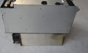
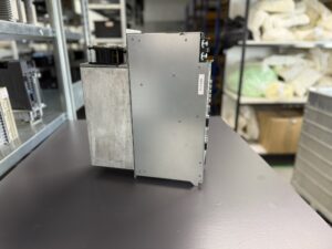
The Okuma MIV08-3-V5 Spindle Drive arrived with a sporadic Alarm 04. In the machine, the error mainly occurred during rapid acceleration, sometimes only after extended operation. Such intermittent faults usually indicate borderline insulation paths, contact problems, or thermally dependent issues in the output stage.
First Assessment
Upon arrival, serial number, previous repairs, and cable routing from the machine protocol were documented. A visual inspection revealed noticeable dust and coolant mist deposits around the output terminals. With the drive powered down, the unit was opened, and the IVPB08-3 power board, the ICB3H control board, the BTB71 interface board, and the MIV08 power module were inspected individually.
Electrical checks included insulation measurement of motor phases to ground, ESR and leakage current test of the DC link capacitors, inspection of gate drivers and optocouplers for symmetry, as well as diode and short-circuit testing of the IGBT bridge.
Fault Pattern
The alarm could not be triggered under cold conditions. After thermal preheating and vibration testing, short current spikes appeared on phases U-V-W. Under the terminal block cover, dark traces were visible along a contaminated insulation path. This is typical of oil mist deposits: under heat and moisture, the breakdown voltage drops, partial discharges occur, and the drive reports a motor line overcurrent. The IGBTs themselves were electrically intact; the root cause was localized around the terminals and in the aged snubber network.
Preventive Repair Process
A comprehensive preventive approach proved most effective. Instead of only fixing the obvious cause, the entire unit was restored to a reliable baseline condition.
- Cleaning
Intensive cleaning of all assemblies in aqueous emulsion, rinsing with deionized water, drying in a convection oven under a defined temperature profile. Old thermal paste was removed and replaced on the power module.
- Power Stage
Load-pulse testing of the IGBT modules, renewal of snubber capacitors and resistors, rework of critical solder joints in the output section. Torque and resistance checks on the terminals.
- Control and Protection Circuits
Preventive replacement of aged optocouplers, gate-driver ICs, and selected capacitors in the driver stage. Verification of current detection and shunt/CT signals for linearity and offset.
- DC Link and Power Supply
Ripple and ESR measurements, replacement of primary electrolytic capacitors with 105°C-rated types. Testing of precharge and discharge circuits.
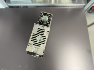
- Cooling and Airflow
Replacement of worn fans, cleaning of heat sinks and airflow channels, renewal of insulation and sealing materials around the terminal block to prevent future contamination.
- Documentation and Checklists
Every step was documented on checklists. Measurements, component batch numbers, torque values, and thermography results were recorded in the test protocol. This procedure, established over many years, ensures traceability and reproducibility.
Test Bench and Verification
After reassembly, the drive was tested on our reference machine equipped with a VAC spindle motor and NC simulator.
- Commissioning
Parameter verification, communication test, reference runs without load.
- Dynamic Tests
Acceleration and deceleration ramps, step responses, repeated load cycles. We monitored phase currents, DC bus voltage, gate signals, and thermal profiles, with special focus on transient overcurrents in the millisecond range.
- Thermal Cycling
Several hours of continuous operation with controlled heating and cooling. The goal was to reproduce the original sporadic fault. After the repair, the current waveform remained stable, no asymmetrical peaks, and no reoccurrence of Alarm 04.
- Safety and Final Checks
Insulation and high-voltage test, emergency stop braking, restart behavior, and complete logging of test values. Finally, the terminal cover was sealed with a moisture- and oil-mist barrier.
Result
The drive proved stable under both cold and hot conditions. The root cause was a combination of contaminated insulation paths at the output terminals and aged damping components in the snubber circuit. With the preventive overhaul, not only was the acute fault eliminated, but the reliability margin was restored.
Preventive Measures for Customers
- Maintain clean electrical cabinets Replace filter mats regularly, keep airflow unobstructed, avoid intake near coolant mist.
- Check fans and temperatures Inspect fans annually, replace in time, monitor heat sink and module temperatures in maintenance schedules.
- Inspect cables and terminals Test motor and ground cables for damage, tighten terminals with proper torque, ensure motor terminal boxes are sealed.
- Protect against moisture and oil mist Check gaskets and covers, avoid direct compressed air cleaning on electronics.
- Perform insulation testing Regular megger testing of motor phases to ground, track values over time.
- Monitor DC link health Inspect capacitors for bulging, measure ripple voltage under load.
- Optimize parameters and acceleration Avoid unnecessary extreme acceleration ramps, reduce stress on power stage.
- Check regeneration circuit Verify brake resistor dimensioning and cabling.
- Keep spare fans and filters in stock Having spare parts on-site reduces downtime.
- Plan preventive overhauls Depending on runtime and environment, schedule a preventive refurbishment every 5–7 years.
Conclusion
Sporadic Alarm 04 messages are rarely accidental. They indicate operation at critical limits, often triggered by contamination, heat, or component aging. With systematic inspection, preventive refurbishment, and rigorous testing, spindle drives can be restored to dependable operation. Ultimately, longevity depends on customer care: clean cabinets, working fans, tight cabling, and timely replacement of wear parts ensure longer service life and fewer unexpected machine stoppages.
For more information about our Okuma repairs, please click here.
📞 Feel free to contact us if you have any questions regarding your Mitsubishi drive technology. Our experienced team is always ready to provide you with expert advice and support.
Technical Specifications (Device Data):
| Parameter | Value |
|---|
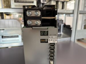
| Model | Okuma MIV08-3-V5 |
| Order number | 1006-2257 |
| Rated output | 7.5 kW (10 HP) |
| Input voltage | 300 VDC (supplied from MPS/MPR power supply) |
| Control voltage | 24 VDC (control supply) |
| Dimensions (H×W×D) | 380 × 100 × 325 mm |
| Weight | approx. 7.3 kg (16.1 lbs) |
| Motor types | VAC motors (VAC 7.5 / 5.5 kW typical) |
Operating Environment & Compatible Devices
- Installed in Okuma CNC machines (lathes, machining centers).
- Works with VAC spindle motors in the 7.5 kW range.
- Requires an external MPS or MPR Power Supply Unit for 300 VDC and 24 VDC supply.
- Communication via Servo Link, Encoder Link and Converter Link with the NC system.
- Operating conditions:
- Ambient temperature: 0–55 °C
- Relative humidity: < 90 % (non-condensing)
- Must be installed in a sealed, dust- and moisture-protected control cabinet.
Functional Description
The MIV08-3-V5 is an inverter spindle drive designed for Okuma VAC spindle motors.
Key functions:
- Controls spindle speed and torque.
- Communicates with the NC controller via Servo Link.
- Monitors current, voltage, temperature, and motor feedback signals.
- Provides protection functions against overcurrent, overload, overheating, and encoder faults.
- Equipped with a 7-segment LED display for status indication, alarms, and warnings.
Alarm Messages and Troubleshooting
| Alarm No. | Description | Cause | Solution |
|---|
| 04 | Motor power line over current | Overcurrent detected in motor line (short, bearing fault, excessive load) | Check motor, replace drive if needed |
| 05 | Inverter overheat | Insufficient cooling, defective fan, high ambient temperature | Check fan, improve cooling |
| 06 | Inverter overload | Load exceeded rating, spindle blocked, incorrect parameters | Reduce load, check servo data |
| 07 | Commercial power source error | Input voltage out of tolerance | Inspect power supply and cables |
| 09 | Motor winding changeover error | Switching error, timeout, servo data mismatch | Inspect motor changeover contactor |
| 10 | Encoder communication error | Defective encoder cable or faulty encoder | Inspect/replace encoder and cable |
| 11 | Encoder error | Position feedback missing | Replace motor encoder |
| 12 | Encoder initialization error | Initialization failed, communication error | Inspect encoder, cables, or replace drive |
| 20 | Motor overheat | Motor exceeded safe temperature | Reduce load, check cooling |
| 32 | Speed deviation too large | Excessive deviation between command and feedback speed | Reduce load, check encoder |
Components
| Name | PCB Marking | Qty |
|---|
| Control board | ICB3H | 1 |
| Power board | IVPB08-3 | 1 |
| Interface board | BTB71 | 1 |
| Power module | MIV08 | 1 |