07.01.2026 by Viktor Siebert
Repair of a Mitsubishi Power Supply Unit MDS-C1-CV-75 with Alarm F
A practical case involving misdiagnosis, prior repairs and system-level damage.
Initial condition on arrival
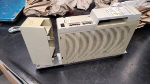
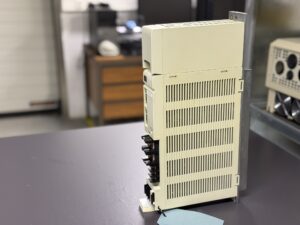
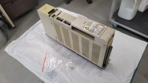
The Mitsubishi Power Supply Unit MDS-C1-CV-75 was received with Alarm F active.
The unit was able to power up, but the startup sequence was not stable and the alarm occurred reproducibly.
From the outside, the power supply initially appeared unremarkable. There were no obvious burn marks or clearly destroyed assemblies. Especially with older power supply units of this series, however, visual inspection alone is not sufficient, as many fault conditions develop internally and only become apparent under load or during detailed analysis.
At an early stage it became clear that the unit had already been repaired previously. The exact scope and quality of these earlier interventions could not be fully reconstructed. No documentation or measurement records were available.
Initial analysis and observations
During the incoming inspection it became apparent that the power supply started up, but did not operate in a stable manner internally. The monitoring functions reacted inconsistently, indicating unstable internal regulation behavior.
In addition, a sporadic noise in the area of energy transfer was noticed during testing. This noise did not occur continuously, but was reproducible and pointed to a long-standing load condition or pre-existing damage. Whether this phenomenon originated from the original operating phase or from previous repair attempts could not be determined with certainty at that time.
What was clear, however, was that the fault was not isolated, but affected the interaction of several internal functions.
Classification of the alarm condition
Alarm F on MDS-C1 series power supply units is not a trivial indication. It generally points to a disturbance within the internal monitoring or supply circuits. In practice, this alarm is often misinterpreted and prematurely attributed to individual components.
In this case, it became very clear that the alarm was not caused by a single, clearly identifiable defective part, but by deviations in internal measurement and regulation conditions. As a result, the protection logic reacted correctly, even though the actual root cause was located deeper within the system.
This type of situation is a common reason why units are repaired multiple times without achieving long-term stability.
Condition after previous repair attempts
As the analysis progressed, it became evident that earlier interventions on the unit had not been carried out in a systematic manner. Several areas showed signs of subsequent work that no longer corresponded to the original design.
Such prior repairs significantly complicate fault diagnosis. Measurement values can no longer be clearly interpreted, reference conditions are missing, and secondary damage often remains undetected. In this case, the original fault had continued to evolve over time, leading to additional issues.
The power supply was in a condition often described in practice as “repaired beyond recovery”: seemingly operational, but technically unstable.
Repair approach and restoration
For this reason, a purely selective repair was deliberately avoided. Instead, a comprehensive system-level restoration of the unit was carried out.
All relevant functional areas were examined, unstable operating conditions were eliminated, and mechanical as well as electrical weaknesses were professionally corrected. Particular attention was paid to restoring stable operating conditions, clean signal behavior, and reproducible measurement results.
In addition, numerous age-related and thermally stressed elements were renewed as a preventive measure to ensure long-term stability. Damaged conductor paths and conspicuous solder joints were professionally reworked.
Only after these measures was the power supply unit able to operate reliably again.
Testing and release
After completion of the repair, the power supply unit underwent extensive testing. This included:
- stable startup under defined conditions
- verification of internal monitoring functions
- load testing over an extended period
- monitoring for any recurrence of Alarm F
The unit showed stable behavior without any abnormalities. Only after successful completion of all tests was the unit approved for return to the customer.
Practical conclusion
This repair case clearly demonstrates that alarm messages on power supply units must always be evaluated in the overall system context. Isolated measures without systematic analysis often lead to secondary damage and unnecessary downtime.
Especially with older Mitsubishi MDS-C1 power supply units, experience is crucial in distinguishing between cause, symptom and consequence. A professional restoration is more time-consuming, but it is the only sustainable solution.
To mentioned Mitsubishi Drive: Mitsubishi Power Supply Unit MDS-C1-CV-75
More details about our Mitsubishi repair services can be found here:
Mitsubishi drive Repair by Industrypart
📞 Feel free to contact us with any questions about your Mitsubishi drive technology.
Our expert team is happy to help!
Technical specifications
| Parameter | Value |
|---|
| Manufacturer | Mitsubishi Electric |
| Model | MDS-C1-CV-75 |
| Device category | Power Supply Unit |
| Input voltage | 3AC 200–230 V, 50/60 Hz |
| Output voltage | DC approx. 270–311 V |
| Rated DC bus current | approx. 30 A |
| Cooling | Forced air cooling |
| Application | CNC servo and spindle systems |
| Production period | approx. late 1990s |
Typical fields of application
- CNC machining centers
- Turning and milling machines
- Machine tools with Mitsubishi MDS-C1 drive systems
- Multi-axis servo and spindle applications
Typical alarm messages (excerpt)
| Alarm | Description | Note |
|---|
| F | Power supply fault | Internal monitoring or supply fault |
| 61 | Power module overcurrent | Overload or internal protection response |
| 68 | Watchdog | Internal process disturbance |
| 6C | Main circuit error | Charging or DC bus issue |
| 72 | Fan stop | Insufficient cooling |
Assembly overview (updated)
| Assembly type | Board designation | Quantity |
|---|
| Control board | RK415D-2 or BN638A309G51 | 1 |
| Power board | RK481B-75 or BN638A104G51 A | 1 |
| Power section | Heatsink assembly only, no separate power board | 1 |