25.03.2026 by Viktor Siebert
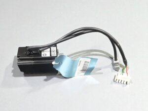
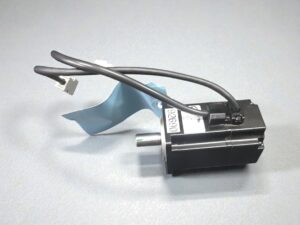
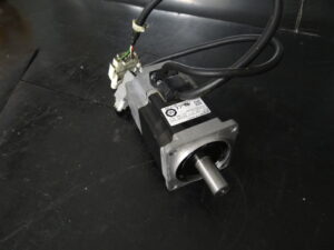
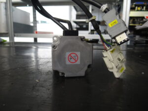
Omron AC servo motor R7M-A20030 with external feedback via a Yaskawa encoder TRD-FY2000
Initial situation and fault pattern.
The repair case involved an Omron AC servo motor R7M-A20030 with external feedback via a Yaskawa encoder TRD-FY2000. The motor was delivered with the clearly stated fault pattern encoder no communication. For incoming inspection, we tested the motor on our test bench with an Omron servo drive R7D-AP04H. The fault pattern was immediately noticeable because the drive could basically be switched on, but the feedback was not established properly. Exactly this combination is often tricky in practice. From the outside, the motor does not initially appear like a classic total failure because the power section, supply and basic function of the test setup are present. What is decisive, however, is that the controller cannot establish proper enable and stable control without usable feedback.
Technically, this kind of fault is not always immediately clear. A communication problem in the feedback can be caused by the encoder itself, by signal transmission, by contact problems, by cable faults or by a disturbance in the evaluation path. The actual damage pattern often does not lie in the motor power section, but in the feedback chain. That is exactly why separating the power section and the feedback during diagnosis is so important.
Incoming inspection and initial diagnosis
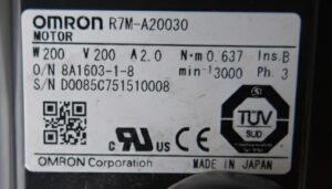
At the beginning, the usual incoming inspection was carried out with visual inspection, nameplate comparison and basic electrical testing. The motor nameplate provided the essential key data. 200 W, 200 V, 2.0 A, rated torque 0.637 Nm and 3000 min⁻¹. This made it clear that the motor basically belongs to a compact high dynamic servo application in which feedback plays a central role for commutation and control quality.
In the next step, the motor was connected to the test bench with the Omron R7D-AP04H. The fault pattern remained reproducible. The feedback did not establish clean communication, while the overall behavior did not indicate a classic winding fault or an obvious short circuit in the power path. This distinction is especially important. A defective motor power path usually shows itself immediately through current anomalies, irregular running or protective shutdowns. Here, the focus was clearly on the feedback circuit.
The initial diagnosis was therefore deliberately directed at three areas. First, the condition and plausibility of the encoder unit. Second, the signal transmission between encoder and controller. Third, the interaction between motor, feedback and enable logic. This was also relevant because documented servo drive faults in this device class clearly distinguish between phase faults in the feedback and complete encoder interruption. In the Omron alarm chapter, fault A.C3 is described as encoder disconnection detected, meaning interruption or short circuit in encoder phases A, B or S.
Technical analysis
From a technical point of view, the feedback in this system is not just an additional signal for position, but a central part of the entire drive function. The controller needs the encoder signals for position detection, speed generation and correct electrical assignment of the motor. If this information is missing or implausible, the drive cannot regulate properly despite the supply being present. In the fault pattern, this matches exactly with the documented Omron faults A.C2 and A.C3. A.C2 stands for phase error in the electrical angle information, A.C3 for interruption or short circuit in the encoder connection.
The cause effect chain was clear in this case. Disturbance in the feedback chain, therefore no stable or usable encoder communication, therefore no reliable signal reference for the control loop, therefore malfunction during startup and no control loop capable of being enabled. That is exactly why such a motor can appear relatively inconspicuous from the outside and still fail completely in the machine. The motor itself does not necessarily have to have winding damage. In many cases, the electrical main function of the motor initially remains intact, while the feedback is the actual cause of failure.
What is also noticeable about this fault pattern is that such systems sometimes still show brief reactions even though actual controllability has already been lost. This explains why the fault often begins as sporadic in operation and later turns into a permanent communication fault. In the workshop, it is then crucial not only to measure the feedback electrically, but to assess it functionally in interaction with the correct drive.
Repair measures and overhaul
The repair focused functionally on the feedback unit and its signal path. The motor was opened for technical processing, the relevant areas were cleaned and the feedback was specifically tested. The decisive point was not to search for the cause only by suspicion in the periphery, but to fully assess the feedback as an assembly. At the same time, the basic motor functions were checked so that no second fault in the power section would be overlooked.
During the repair process, the encoder side function was restored, the signal transmission was checked and the affected functional areas were technically returned to a stable condition. In addition, contact relevant interfaces were inspected and all connections critical for feedback were reworked. As a preventive measure in such cases, it is important not only to eliminate the immediate fault, but also to assess the typical weak points of the feedback. These include plug connections, strain relief, cable condition, proper shielding and mechanically stable mounting in the feedback area.
Final function test
After the repair, the final test was carried out again with the Omron R7D-AP04H on the test bench. The aim was to check specifically whether the feedback was again detected stably and whether the motor could be reproducibly enabled, accelerated and controlled. In on off behavior, the motor had to react without communication interruptions. At low speed, it was especially important that no signal offset and no unsteady control behavior were visible anymore. In the medium speed range, attention was paid to even running, clean feedback and stable speed behavior. In the upper test range, the focus was on signal consistency.
In addition, signal stability was checked under several start stop cycles. Such tests are important because an encoder fault can occur not only as a permanent failure, but also as a thermally or mechanically influenced interruption. After the repair, the motor showed stable behavior, the feedback remained plausible and the drive could again be operated properly on the test bench.
Conclusion
The damage was functionally in the feedback and not primarily in the motor power section. That explains exactly why the drive did not appear like a classic total failure from the outside, but still could no longer function properly in the system. Through targeted repair of the encoder side function and final testing with the matching Omron drive, the fault pattern could be processed in a technically clean way. The repair is especially sustainable when, in addition to the actual feedback, the signal carrying interfaces and the entire feedback path are also taken into account. This helps avoid the same fault recurring again after a short operating time.
Information about the mentioned Servopack and Servomotor:
More information about our Omron repairs can be found here.
📞 Feel free to contact us if you have any questions regarding your Omron drive technology. Our experienced team is always ready to assist you.
Technical specifications
Motor
| Field | Value |
|---|
| Manufacturer | Omron |
| Device type | AC servo motor |
| Model designation | R7M-A20030 |
| Series | R7M |
| Power | 0.2 kW |
| Input voltage | 3~ 200 VAC from servo drive |
| Output voltage | not applicable |
| Rated current | 2.0 A |
| Control type | controlled servo operation with external feedback |
| Feedback | Yaskawa TRD-FY2000, incremental encoder |
| Cooling | self cooling, approx. naturally cooled |
| Protection class | approx. industrial closed motor design |
| Ambient temperature | approx. 0 to 40 °C |
| Mounting | flange mounting |
| Origin | Japan |
| Product status | older existing component, still found in service environments |
Drive
| Field | Value |
|---|
| Manufacturer | Omron |
| Device type | AC servo drive |
| Model designation | R7D-AP04H |
| Series | R7D |
| Power | approx. 0.4 kW |
| Input voltage | approx. 200 to 230 VAC |
| Output voltage | 3~ PWM motor output, approx. up to 200 VAC |
| Rated current | approx. 4 A |
| Control type | servo controller with closed loop control via encoder |
| Feedback | encoder A, B, S signals |
| Cooling | convection or cabinet cooling, depending on installation situation |
| Protection class | control cabinet device |
| Ambient temperature | approx. 0 to 55 °C |
| Mounting | vertical in control cabinet |
| Origin | Japan |
| Product status | older servo electronics in existing plant environments |
Operating environment and possible applications
This drive is typically used in compact axes with high dynamics, for example in handling units, small feed axes, packaging machines, assembly systems or special purpose machines. Based on its key data, the R7M-A20030 motor is clearly designed for precise motion tasks. The R7D-AP04H drive belongs in a classic servo system with encoder feedback and protective logic for overcurrent, overspeed, regeneration, phase faults and encoder interruption.
Typical years of manufacture are realistically in the older to mid age existing machinery range. In such systems, the issue is often not the pure motor itself, but the aging of the feedback, the connectors or the shielding. For the control cabinet, proper grounding, separate routing of power and signal cables, stable supply and sufficient thermal reserves are important. Electrically critical are voltage drops, contact problems and disturbances in the encoder path. Thermally critical are excessive ambient temperatures and insufficient heat dissipation at the drive.
Functional description
The basic function of the system is the controlled conversion of line supply into precise motor motion in terms of speed and position. The power section of the drive generates the three phase motor output. The controller compares command value and feedback value. The feedback supplies the signals necessary for commutation, angle assignment, speed generation and motion monitoring.
In the interaction of power section, control and feedback, the encoder is safety relevant for stable operation. Without plausible feedback, the drive cannot correctly detect the motor position. In the documented Omron alarm concept, this includes A.C2 phase error detected and A.C3 encoder disconnection detected. A.C3 explicitly describes an interruption or short circuit in encoder phase A, B or S.
Enable and protective logic work together. In case of faults, alarm messages are output, the power stage is shut down and the fault code is displayed. Documented faults include overcurrent, regeneration error, overvoltage or undervoltage, overload, overtemperature, phase error, encoder interruption and deviation counter error.
Safety note: Before opening or unplugging connectors, always isolate from power, secure against restart, wait the discharge time and verify absence of voltage. Measurements on live parts must only be carried out by qualified electrical personnel with suitable equipment and according to local rules.
Alarm messages and troubleshooting
| Alarm code | Description | Possible cause | Recommended measure |
|---|
| A.04 | Parameter setting error | Servo motor does not match the servo drive | Perform type check and check parameterization |
| A.10 | Overcurrent | Short circuit, ground fault, fault in power section | Check motor cable, insulation and wiring |
| A.30 | Regeneration error | Defect in regeneration circuit | Check regeneration path and resistor |
| A.32 | Regeneration overload | Excessive regenerative energy | Calculate braking energy and check braking resistor and deceleration ramp |
| A.40 | Overvoltage or undervoltage | DC bus outside target range | Check supply voltage and incoming power |
| A.51 | Overspeed | Motor speed above permissible value | Check encoder and parameterization, limit command value |
| A.70 | Overload | Permanently excessive torque | Check load and increase acceleration time |
| A.73 | Dynamic brake overload | Braking resistor overloaded during braking operation | Reduce braking frequency and inertia |
| A.74 | Inrush resistance overload | Main supply switched on and off too often | Reduce switching frequency |
| A.7A | Overheat | Impermissible temperature rise in the drive | Check cooling and ambient temperature |
| A.bF | System error | Fault in control or regulation circuit | Check or replace drive |
| A.C1 | Runaway detected | Motor rotates opposite to the command | Check motor and encoder wiring |
| A.C2 | Phase error detected | Electrical angle detected incorrectly | Check feedback and plug connection |
| A.C3 | Encoder disconnection detected | Encoder A, B or S interrupted or short circuited | Check encoder, cable, connector and signal path |
| A.d0 | Deviation counter overflow | Excessive control deviation | Check mechanics, load, gain and parameters |
| CPF00 | Parameter Unit transmission error 1 | Communication to operator unit faulty after power on | Check contact and drive |
| CPF01 | Parameter Unit transmission error 2 | Communication timeout | Check operator unit, contact and drive |
| A.91 | Overload warning | Pre warning before A.70 | Check load and operating profile |
| A.92 | Regeneration overload warning | Pre warning before A.32 | Check deceleration profile and braking energy |
Assembly overview
| Assembly | Functional designation | Function | Notes for inspection or repair |
|---|
| Stator and rotor | Motor power section | Generates torque and rotary motion | Check winding condition, insulation value and running behavior |
| Feedback | Encoder Yaskawa TRD-FY2000 | Supplies position and speed information | Check signal quality, supply, connector and cable condition |
| Motor connection | Power connection | Transfers U, V, W to the motor | Check contact condition, transition resistances and conductor condition |
| Encoder interface | Feedback connection | Transfers A, B, S and supply | Especially susceptible to contact and cable faults |
| Bearing system | Motor bearing system | Ensures smooth running and correct mechanics | Check noise, play and thermal behavior |
| Housing and flange | Mechanical base | Centering, protection and mounting | Check fit, sealing and damage |
| Servo controller | Omron R7D-AP04H | Power amplification and regulation | Check alarm history, supply and cooling |
| Protective logic | Internal controller monitoring | Overcurrent, temperature, regeneration, encoder faults | Always compare fault pattern with feedback and supply |