08.11.2025 by Viktor Siebert
Repair of an Okuma Servo Drive MIV0204-1-B1 with the ordernumber 1006-2231
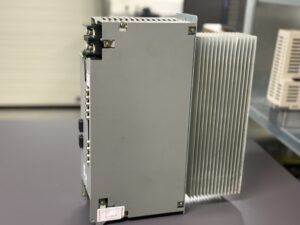
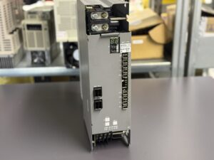
Repair of an Okuma Servo Drive MIV0204-1-B1
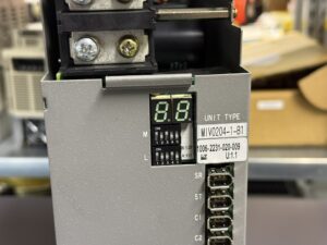
The Okuma Servo Drive MIV0204-1-B1, order number 1006-2231, was tested in a CNC machine. When powered on, the CNC control displayed Alarm 1151-03 “Alarm A”, while the inverter showed alternating messages “E.L.” and “13” on the 7-segment display. According to the MIV manual, this corresponds to an Inverter Bridge Error (Alarm 13), which indicates a malfunction within the power output stage
Alarm 13 – Inverter Bridge Error
According to the official alarm table (Okuma MIV Manual, section 4-3-1, page 19), Alarm 13 is triggered when a malfunction is detected in the power bridge or gate-signal section. Possible causes include:
- defective gate drivers or insulation faults between control and power stage,
- short circuit in the IGBT power module,
- damaged gate-signal wiring or open circuit in the drive path,
- irregular feedback in the DC-bus or overcurrent detection circuit
When such a condition is detected, the inverter immediately disables the power stage via the error-status register to protect the transistors from destruction.
Diagnosis and Repair Procedure
After arrival, the unit underwent a full visual and electrical inspection. Dust deposits near the heat sink and power modules indicated thermal stress. The 7-segment fault “E.L. 13” was reproduced during test bench startup. The unit was then opened and analyzed on board level under laboratory conditions.
- Primary DC-Bus Check
The 300 V DC input from the MPS/MPR supply was stable, confirming a healthy power source and eliminating DC-link faults.
- Gate-Signal Measurement
Oscilloscope readings showed one channel without valid PWM output. The affected channel belonged to the second (M-) axis.
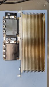
- IGBT Module Testing
Isolation and dynamic tests revealed leakage current on one phase transistor arm. This confirmed a defective power module consistent with Alarm 13.
- Control Board (ICBI Board)
Further testing showed irregular switching levels from the gate-driver IC on the ICBI board. The board was completely refurbished in our workshop.
- Component Replacement and Final Test
After replacing the faulty transistor module and driver components, the inverter was reassembled, cleaned, and subjected to full insulation and high-voltage testing. It was then operated on our original test stand with two BL-MC servo motors. All parameters remained stable, and no alarm reappeared during several hours of thermal load testing.
Preventive Measures
The analysis showed that thermal aging of the power modules and insufficient cooling are common root causes for this type of failure. Therefore, every overhaul includes:
- replacement of all IGBT power modules,
- renewal of driver and DC-link capacitors,
- cleaning and re-application of thermal compound,
- verification of all auxiliary voltages (±12 V / +24 V),
- extended long-term endurance tests under full load.
Conclusion
The Okuma inverter MIV0204-1-B1 was successfully restored to full function after extensive repair.
The fault “E.L. 13” (Inverter Bridge Error) was traced to a defect within the power stage and gate-driver circuit. After replacement of the affected assemblies, the unit operated reliably on the test bench under real CNC load conditions.
Price and Delivery Time for Okuma Servo Drive MIV0204-1-B1 with the ordernumber 1006-2231
For more information about our Okuma repairs, please click here.
📞 Feel free to contact us if you have any questions regarding your Okuma drive technology. Our experienced team is always ready to provide you with expert advice and support.
Technical Specifications Okuma MIV0204-1-B1
Manufacturer: Okuma Corporation
Device Type: MIV Servo Inverter Unit (dual-axis module)
Okuma Order No.: 1006-2231
Number of Axes: 2 (L-axis 2.0 kW, M-axis 4.0 kW)
Total Power: approx. 4 kW (continuous)
Input Voltage: 300 V DC (from MPS/MPR power supply module)
Control Voltage: 24 V DC
Compatible Motors: Okuma BL and PREX servo motors
Display: 7-segment LED (status, alarms, warnings)
Communication: Servo Link, Encoder Link, Converter Link
Control Board: ICBI Inverter Control Board (integrated)
Cooling: Forced air with aluminum heat sink
Housing: Aluminum modular construction
Drive Topology: IGBT transistor bridge with overcurrent protection
Monitoring: DC bus voltage, phase current, gate signal, temperature
Typical Configuration
- MPS/MPR Power Supply Unit (300 V DC)
- BL-MC or PREX motors 2.0 – 4.0 kW
- OSP-U10/U100 control systems
Alarm List Okuma MIV Series (Excerpt for MIV0204-1-B1)
| No. | Name | Description / Meaning | Corrective Action |
|---|
| 01 | Power Supply Unit Error | Fault in power supply (DC voltage, AC input, overheating, or control error) | Check supply voltage, replace MPS/MPR unit if necessary |
| 02 | Converter Link Error | Communication fault with power supply (interruption or timeout) | Check link cable, replace MIV or MPS/MPR |
| 03 | Inverter DC Bus Voltage Error | DC bus voltage too high or too low | Check mains voltage, replace MIV or MPS/MPR |
| 04 | Motor Power Line Overcurrent | Overcurrent detected in motor circuit | Inspect motor and cables, replace MIV if required |
| 05 | Inverter Overheat | Inverter temperature exceeded limit | Check cooling, replace MIV unit |
| 06 | Inverter Overload | Electronic overload protection activated | Reduce load torque, check cooling |
| 07 | Commercial Power Source Error | Input voltage out of tolerance | Check supply |
| 09 | Motor Winding Changeover Error | Fault in motor winding changeover | Check contactor or wiring |
| 10 | Encoder Communication Error | Communication failure between encoder and inverter | Check encoder or link cable |
| 11 | Encoder Error | Motor encoder failed to detect position | Check or replace encoder |
| 12 | Encoder Initialization Error | Initialization error of motor encoder | Replace encoder or cable |
| 13 | Inverter Bridge Error | Fault in power device or gate signal circuit | Check power module, gate driver, replace defective parts |
| 14 | Motor Overcurrent Error | Abnormal current in power stage | Check motor or power stage |
| 20 | Motor Overheat | Motor temperature too high | Inspect cooling, motor, and encoder |
| 21 | Servo Link Communication Error | Communication fault with CNC controller | Check link cable, replace FCP board if needed |
| 22 | Servo Link Cable Breakage | Servo link cable disconnected | Replace cable |
| 23 | Servo Link Protocol Error | Invalid communication format or timing | Check CNC software |
| 24 | Servo Data Error | Invalid parameter data | Check servo data, replace MIV if necessary |
| 31 | Speed Over | Actual speed too high | Check drive and encoder |
| 32 | Speed Deviation Too Large | Excessive deviation between command and actual speed | Check encoder or mechanical load |
| 38 | Motor Overload (Thermal Relay) | Motor overload protection activated | Reduce torque load |
| 40 | Tandem Control Communication Error | Communication fault between master and slave axis | Check link, replace MIV if needed |
Technical Description and Function
The Okuma MIV0204-1-B1 is a dual-axis inverter module used within the modular MIV servo system. It supplies two motor axes (L-axis = 2.0 kW, M-axis = 4.0 kW) and receives its main power through the 300 V DC intermediate circuit, generated by a central MPS/MPR power supply unit.
An integrated control board (ICBI board) regulates the motor current and handles communication with the CNC through the servo link.
During operation, the inverter generates and monitors several internal voltages:
- +24 V for logic and communication
- ±12 V for internal signal processing
- +5 V for encoder supply
All voltages are continuously monitored by the CPU. Even small deviations or PWM synchronization faults will activate protective shutdown to prevent further damage.