10.02.2026 by Viktor Siebert
Okuma Power Supply MPS20 with Alarm 04 and A.01 Overvoltage (1006-2201)
Initial Situation
An Okuma Power Supply MPS20 (1006-2201) arrived at our workshop with a clear but technically challenging fault description from the customer:
Alarm 04 Commercial power source error / Main circuit power source error.
The fault did not occur permanently but intermittently. This type of failure is particularly critical in practice because it is often difficult to reproduce and leads to unpredictable machine downtime.
During the first power-up test, unusual behavior was observed. The power supply did not start at all. There was no DC bus build-up, no stable initialization, and no proper startup of the MCS power system.
Initial Diagnosis and Findings
After opening the unit, a systematic visual inspection and measurement process was carried out:
- Input voltages L1/L2/L3 present and symmetrical
- External AC reactor connected correctly
- No visible damage such as burn marks or ruptured components
However, after several measurement cycles and partial thermal relaxation, the MPS20 suddenly powered up. The DC bus voltage built correctly and the basic supply was present.
At the latest during the CNC functional test, the next alarm occurred:
A.01 Overvoltage (DC overvoltage).
This alarm clearly indicates that the regulation of the DC bus voltage is no longer functioning correctly or that the regenerative circuit is operating uncontrollably.
Advanced Troubleshooting
At this stage it was evident that this was not a pure mains supply issue, but rather an internal regulation or power stage fault.
The troubleshooting process was therefore extended to a deeper analysis of the internal assemblies:
- Measurement of DC bus voltage under load and no-load conditions
- Analysis of gate control signals to the power semiconductors
- Comparative measurements between reference values and actual behavior
A decisive finding emerged:
The power stage was no longer being driven correctly. The gate signals were unstable, partially delayed, and at times outside specification.
Root Cause Component Aging in the Drive Circuit
The root cause was located not in the power semiconductors themselves, but in the gate drive and control circuitry of the power stage:
- Aged components in the gate driver and auxiliary supply circuits
- Drift in resistor and capacitor values over time
- Thermally induced instability after many years of operation
These aging effects caused the regenerative control to lose stability. As a result, the DC bus voltage could rise uncontrollably, directly triggering A.01 Overvoltage.
Repair Actions
After clear fault localization, the following repair steps were carried out:
- Replacement of aged components in the power stage drive section
- Preventive replacement of thermally stressed components
- Re-soldering of critical power and ground connections
- Cleaning of circuit boards, heat sinks, and airflow paths
This was followed by a comprehensive functional test:
- Multiple cold and warm start cycles
- Load simulation with regenerative braking scenarios
- Long-term test with continuous DC bus monitoring
Result:
Stable startup behavior, no overvoltage condition, and no recurrence of Alarm 04 or A.01.
Price and Delivery Time for Okuma Power Supply MPS20 (1006-2201)
For more information about our Okuma repairs, please click here.
📞 Feel free to contact us if you have any questions regarding your Okuma drive technology. Our experienced team is always ready to provide you with expert advice and support.
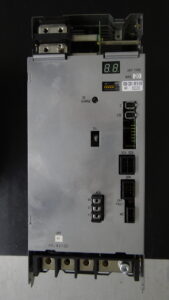
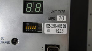
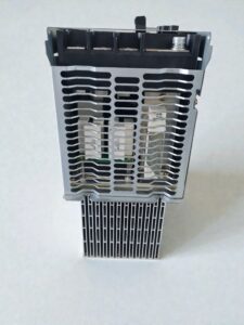
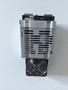
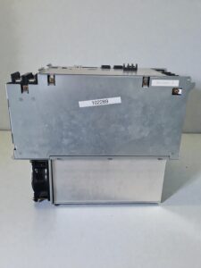
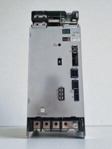
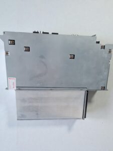
Okuma Power Supply MPS20 (1006-2201)
Device Overview
| Item | Description |
|---|
| Manufacturer | Okuma |
| Device Type | Regenerative DC Power Supply Unit |
| System / Series | Okuma MCS |
| Model | MPS20 |
| Okuma Part Number | 1006-2201 |
| Power Rating | 20 kW |
| Status | End of Life (EOL) |
| Application | Supply for servo and spindle drives |
Functional Description
| Function | Description |
|---|
| DC Bus Generation | Generation and stabilization of approx. 300 V DC bus voltage |
| Regenerative Operation | Active feedback of braking energy into the mains |
| Voltage Regulation | Continuous monitoring and regulation of DC bus voltage |
| Protection Functions | Overvoltage, undervoltage, overcurrent, overtemperature |
| Communication | Converter link to MIV inverter units |
| Energy Efficiency | Reduced power loss due to regenerative design |
Electrical Specifications
| Parameter | Value |
|---|
| Input Voltage | 3-phase 200–230 V AC |
| Line Frequency | 50 / 60 Hz |
| Rated Power | 20 kW |
| DC Bus Voltage | approx. 300 V DC |
| Control Voltage | 24 V DC |
| Regeneration Type | Power Regeneration Type |
| Required Reactor | MPS20-ACL (1006-2281) |
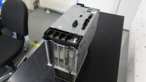
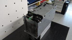
Mechanical Data
| Item | Value |
|---|
| Design | Modular construction |
| Cooling | Forced air cooling, internal fan |
| Mounting | Control cabinet mounting |
| Weight | approx. 9–10 kg |
| Service Access | Front side |
Connections & Interfaces
| Connection | Function |
|---|
| L1 / L2 / L3 | 3-phase AC input |
| P / N | DC bus output to MIV modules |
| CN1 | Converter link communication |
| ACL | External AC reactor connection |
| PE | Protective earth |
| LED Display | Status and alarm indication |
Internal Assemblies
| Assembly | Designation | Function | Service Notes |
|---|
| Control Board | PSB / PSB2 / PSB3 | Regulation and monitoring | Aging-sensitive capacitors |
| Power Board | PSPB20 | Power stage drive control | Critical for overvoltage faults |
| Interface Board | BTB | Signal and power distribution | Check connectors |
| Power Stage | 20 kW Power Unit | DC generation and regeneration | High thermal load |
Relevant Alarm Messages
| Code | Description | Meaning | Typical Cause |
|---|
| 01 | DC Overvoltage | DC bus too high | Faulty control or regeneration |
| 02 | DC Undervoltage | DC bus too low | Supply or reactor issue |
| 03 | Phase Loss | Missing phase | Mains supply fault |
| 04 | Commercial power source error | Main circuit supply fault | Mains or power stage |
| 09 | Power Device Fault | Power semiconductor fault | IGBT or gate drive |
| 11 | Regeneration Error | Regeneration malfunction | Control or reactor |
| 13 | Heat Sink Overheat | Overtemperature | Fan or contamination |
| 14 | Converter Link Error | Communication fault | Cable or control board |
Fault Description in This Case
| Item | Description |
|---|
| Customer Alarm | Alarm 04 – Commercial power source error |
| Initial Condition | Power supply would not start |
| Secondary Fault | A.01 Overvoltage during CNC test |
| Root Cause | Defective power stage drive control |
| Technical Reason | Component aging in gate drive circuitry |
| Effect | Uncontrolled rise of DC bus voltage |
Repair Measures Performed
| Action | Description |
|---|
| Component Testing | Measurement of all relevant voltage and gate signals |
| Replacement | Aged components in drive circuitry |
| Rework | Re-soldering of thermally stressed joints |
| Cleaning | Heat sinks, boards, airflow paths |
| Functional Test | Cold start, warm start, load and regeneration tests |
Preventive Recommendations
| Measure | Benefit |
|---|
| Regular Cleaning | Prevents thermal damage |
| Fan Inspection / Replacement | Avoids overheating |
| DC Bus Monitoring | Early detection of regulation issues |
| Visual Board Inspection | Identification of aging effects |
| Scheduled Maintenance | Extended service life |