15.12.2025 by Viktor Siebert
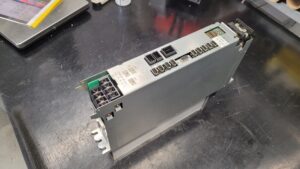
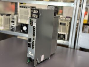
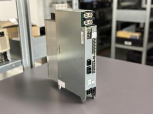
Repair of an Okuma MIV0404A-1-B5 Order 1006-2332 Servo Drive Unit with DC Bus Disturbance AL 03
The Okuma Servo Drive MIV0404A-1-B5 arrived at our facility with alarm AL 03 and the machine message FB 1156 13 indicating an unstable DC bus voltage of the Z axis. The machine had stopped immediately after power up and could not be returned to operation. The customer initially suspected a malfunction in the power supply unit, since the error suggested fluctuations in the DC bus. The MIV unit itself clearly reported alarm AL 03, which points to a disturbance in the internal DC bus or its monitoring circuit.
Upon arrival, the unit was subjected to our standardized incoming inspection. A visual inspection and first measurement points showed no obvious thermal damage, but several values indicated irregularities in bus stability. The behavior was reproducible, though not continuous, which is typical for DC bus faults that manifest under certain load or initialization conditions. Such fluctuations can be caused by axis dynamics as well as gradual deviations within the bus circuitry.
The device was completely disassembled and cleaned. The DC bus components were a central focus since they directly stabilize the internal supply voltage. During simulated load cycles the unit showed conditions that prevented reliable operation. The protection circuits responded correctly and placed the inverter into a fault state. This is a common phenomenon in older units where components age and their electrical characteristics shift over time. Resulting voltage deviations are interpreted by the inverter as under or overvoltage.
During the repair process critical sections were reevaluated and affected components were restored. After completion of the work the inverter was tested on our Okuma test benches. These tests include monitoring DC bus stability, response under simulated mechanical load and verification of communication between MIV and the power supply. Following the repair, the unit showed a stable bus voltage with no recurrence of the alarm. Even during repeated load cycles the voltage remained within the specified tolerance range.
The MIV0404A-1-B5 then underwent several hours of continuous operation. The DC bus operated within normal limits and all protection functions responded correctly. The Z axis could be simulated without error and the unit demonstrated stable and predictable behavior. The customer received the repaired unit together with a complete test report.
Preventive Measures
Regular inspection of the cooling system
Cleaning of connectors and supply sections
Verification of grounding and line quality
Monitoring of load behavior especially for Z axis configurations
Replacement of aging bus components as part of preventive maintenance
Conclusion
A stable DC bus is essential for reliable operation of Okuma MIV series drives. Early maintenance and periodic inspection help prevent failures and extend the service life of the equipment.

Price and Delivery Time for Okuma MIV0404A-1-B5 Order 1006-2332 Servo Drive Unit
For more information about our Okuma repairs, please click here.
📞 Feel free to contact us if you have any questions regarding your Okuma drive technology. Our experienced team is always ready to provide you with expert advice and support.
Technical Specifications
| Feature | Value |
|---|
| Manufacturer | Okuma |
| Model | MIV0404A-1-B5 |
| Order number | 1006-2332 |
| Device type | 2 axis inverter unit for L and M axis |
| Power per axis | 4.0 kW |
| Input voltage | 300 VDC supplied by external MPS or MPR power supply |
| Control voltage | 24 VDC |
| Communication | Servo Link, Encoder Link, Converter Link |
| Compatible motors | BL motors, PREX motors |
| Weight | approx. 5.5 kg |
| Cooling | Convection cooling through housing |
| Control logic | ICB1 control board |
| Manual reference | Okuma MIV Manual, Alarm Table P 21 |
Operating Environment and Compatible Equipment
The MIV0404A-1-B5 is commonly used in Okuma CNC machines of the OSP U100 and OSP E100 series. Typical applications include vertical and horizontal machining centers and lathes with Z axis configurations that return significant braking energy into the DC bus. The MIV units operate together with MPS or MPR power supply units that provide the 300 VDC bus. The drives control BL and PREX motors in the power range up to 4 kW.
Functional Description
The inverter converts the rectified DC bus voltage into a three phase AC output for the servomotors. The internal control system handles command processing, encoder feedback via Encoder Link and comprehensive protection functions for overcurrent, undervoltage, overvoltage, thermal load and communication errors. The DC bus acts as an energy buffer that supplies the inverter and also absorbs regenerative energy from decelerating axes. If the DC bus becomes unstable, the protection logic activates and generates alarm AL 03.
Alarms and Troubleshooting
| Code | Description | Cause | Solution |
|---|
| AL 03 | Inverter DC bus voltage error | Bus voltage above or below threshold | Check supply, inspect DC bus components, test or replace MIV unit |
| AL 01 | Power supply unit error | MPS or MPR detected an error | Check supply voltage, test power supply |
| AL 02 | Converter link error | Communication problem with power supply | Check cable and connectors |
| AL 04 | Motor line overcurrent | Motor side overload | Inspect motor and mechanical load |
| AL 05 | Inverter overheat | Temperature too high | Check cooling and cleanliness |
| AL 06 | Inverter overload | Electronic overload | Verify axis parameters, review mechanical load |
| AL 07 | Commercial power source error | Input power outside tolerance | Check line quality |
| AL 10 | Encoder communication error | Encoder link disturbance | Inspect cables and connectors |
| AL 12 | Encoder initialization error | Initialization process failed | Check encoder link and wiring |
| AL 20 | Motor overheat | Motor or encoder temperature condition | Test motor and thermal load |
Components
| Assembly | Marking on PCB | Function | Notes |
|---|
| Control board | ICB1H or ICB1F | Central control of the drive, signal processing, communication | Visual inspection recommended for discolorations or solder issues. |
| Power board | IVP0404 | Drives the power stage, processes motor currents | Load testing required due to component drift over time. |
| Connection board | BTB71 | Connection between control and power sections | Inspect connectors and traces for contact issues. |
| Power stage | MIV0404 | Converts DC voltage into three phase motor currents | Requires careful evaluation of thermal load and switching behavior. |