30.12.2025 by Viktor Siebert
Repair of an Okuma MIV04-1-B3 rem 1006-2214 Servo Drive Unit with recurring axis faults A.L. 06 and A.L. 28
Initial situation and fault pattern in the CNC machine.
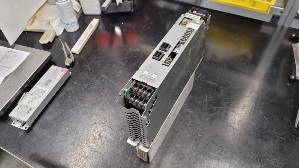
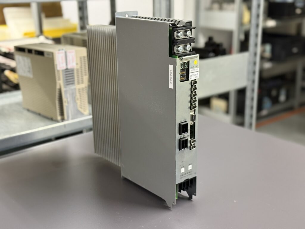
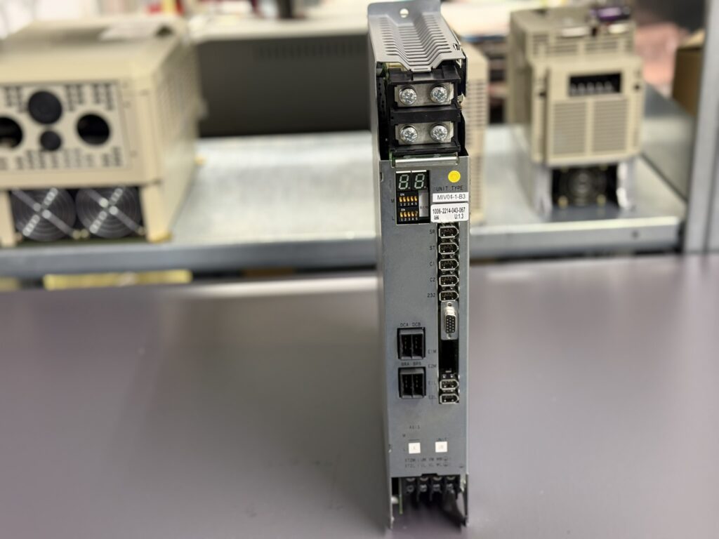
The Okuma drive unit MIV04-1-B3 with part number 1006-2214 was sent in by the customer with the report that unstable axis movements and recurring alarms occurred during operation. The unit was tested directly in a CNC test machine in order to reproduce the real machine behavior as accurately as possible. Even during this test, clear differences in the behavior of the individual axes became apparent.
On the Z axis, alarm A.L. 06 occurred sporadically, even while the axis was at standstill. As soon as an attempt was made to move the axis, alarm A.L. 28 appeared reproducibly. On the Y axis, movement was initially possible, but it was accompanied by strong mechanical noises and noticeable vibrations. After a short time, operation on this axis also stopped with alarm A.L. 06. In addition, it was noticeable that the integrated fan did start up, but produced clearly audible running noises.
This combination of electrical alarms, mechanically perceptible symptoms, and thermal abnormalities indicated at an early stage that this was not a simple parameter or wiring issue.
Technical classification of the relevant alarm messages
Alarm A.L. 06 in the Okuma MIV series is defined as an inverter overload. It is triggered when the electronic overload protection responds because the inverter is operated above its permissible load limit for a certain period of time. Possible causes include increased friction, faulty current measurement, thermal problems, or internal aging effects in the power electronics.
Alarm A.L. 28 stands for a DIFF Over fault. This occurs when the position deviation between the commanded value and the actual value becomes too large. Typical causes include unstable control loops, distorted current signals, encoder problems, or power stages that are no longer able to drive the motor cleanly. In combination with strong noises and vibrations, this alarm must be regarded as particularly critical, as it can indicate both electrical and mechanical instabilities.
Detailed repair story from the workshop
After removal from the test machine, the MIV04-1-B3 was first subjected to a thorough visual inspection. Even at this stage, significant contamination was found in the area of the cooling channels, as well as deposits on the fan and heat sinks. The fan itself was running mechanically rough, which explained the previously observed noises and indicated reduced cooling performance.
The next step was the electrical input inspection. The control voltages were within tolerance, but under load, noticeable fluctuations were observed in the current feedback. These deviations did not occur constantly, but increased with rising operating temperature. This behavior explains why alarm A.L. 06 was triggered partly at standstill and partly only after movement.
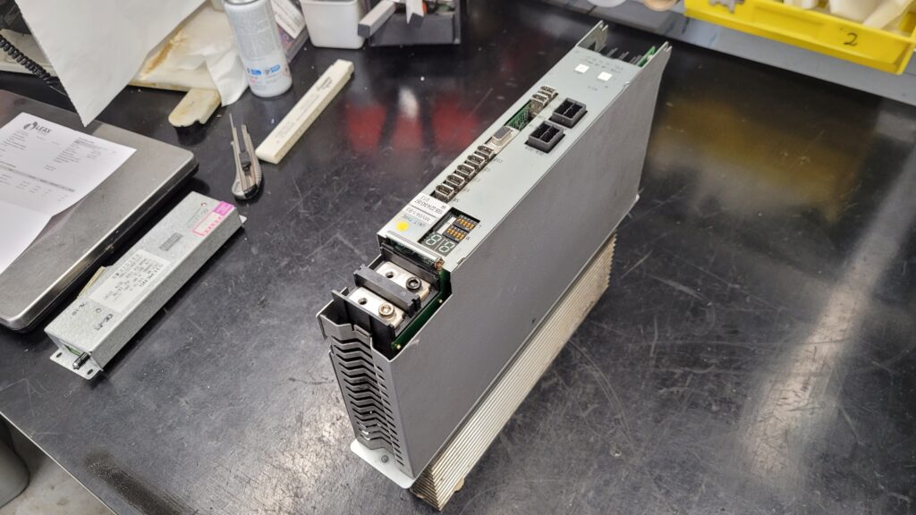
The power board and the power section were then removed and tested separately. It became apparent that individual assemblies were thermally stressed significantly more than intended. Age-related changes in the power electronics caused the current regulation to no longer operate cleanly. As a result, unstable control loops developed, which manifested themselves on the machine as vibrations, noises, and ultimately as the A.L. 28 DIFF Over fault.
In parallel, the ICB1 control board was inspected. Here it was particularly important to ensure that no faulty reference signals or disturbed communication signals to the OSP control were present. After cleaning, testing, and targeted repair measures, the control board could be classified as stable.
A key part of the repair was the preventive replacement of the fan. Its irregular running characteristics would have led to thermal problems again in the long term. After replacement and complete cleaning of all cooling surfaces, the unit was reassembled.
Final tests under real operating conditions
After completion of the repair, the MIV04-1-B3 was once again operated in the CNC test machine. Both the Z axis and the Y axis now showed smooth running behavior without unusual noises or vibrations. The current profiles remained stable, even under prolonged load and repeated acceleration and deceleration cycles. Neither alarm A.L. 06 nor A.L. 28 occurred again.
Special attention was paid to long-term thermal tests. The temperatures in the power section remained within the specified limits, confirming that the cooling system was once again working reliably and that the electronics were no longer entering critical operating ranges.
Preventive measures for the user
Regular cleaning of drive units and cooling channels
Early replacement of fans in case of increased noise levels
Inspection of the control cabinet situation and ambient temperature
Avoidance of continuous operation close to the rated power limit
Regular functional checks at the first signs of vibrations or unusual noises
Conclusion
The repair case of the Okuma MIV04-1-B3 clearly demonstrates how closely electrical, thermal, and mechanical effects are interlinked in modern servo drives. Alarms such as A.L. 06 and A.L. 28 are often not isolated issues, but rather indicators of a gradual aging process within the power electronics. Through systematic diagnosis, professional repair, and realistic testing, full machine availability can be reliably restored and secured in the long term.
Price and Delivery Time for Okuma MIV04-1-B3 Servo Drive Unit 1006-2214
For more information about our Okuma repairs, please click here.
📞 Feel free to contact us if you have any questions regarding your Okuma drive technology. Our experienced team is always ready to provide you with expert advice and support.
Technical Specifications
| Parameter | Value |
|---|
| Manufacturer | Okuma |
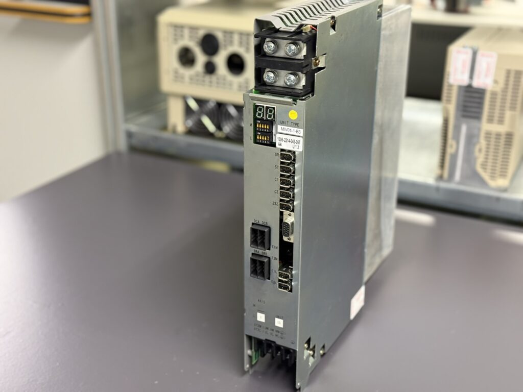
| Model | MIV04-1-B3 |
| Okuma part number | 1006-2214 |
| Device type | Servo Drive Unit |
| Axes | 1 axis |
| Series | MIV Series |
| Rated power | approx. 4.0 kW |
| Supply | DC intermediate circuit |
| DC bus voltage | approx. 300 V DC |
| Control voltage | 24 V DC |
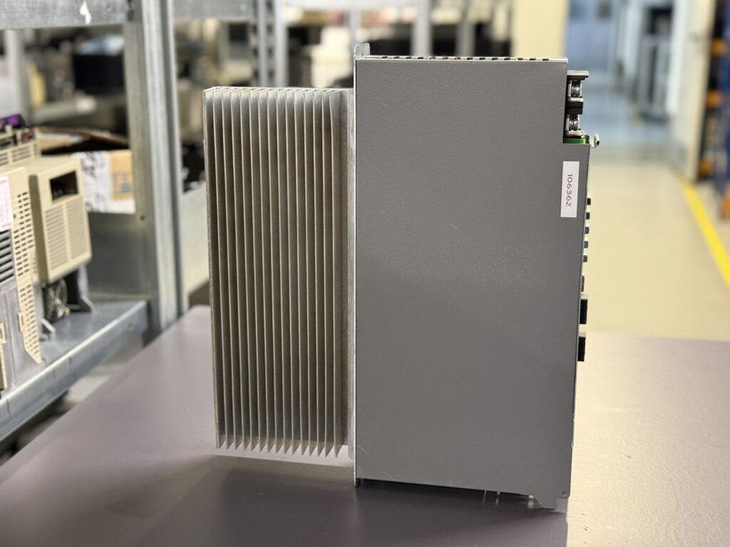
| Cooling | Forced air cooling with internal fan |
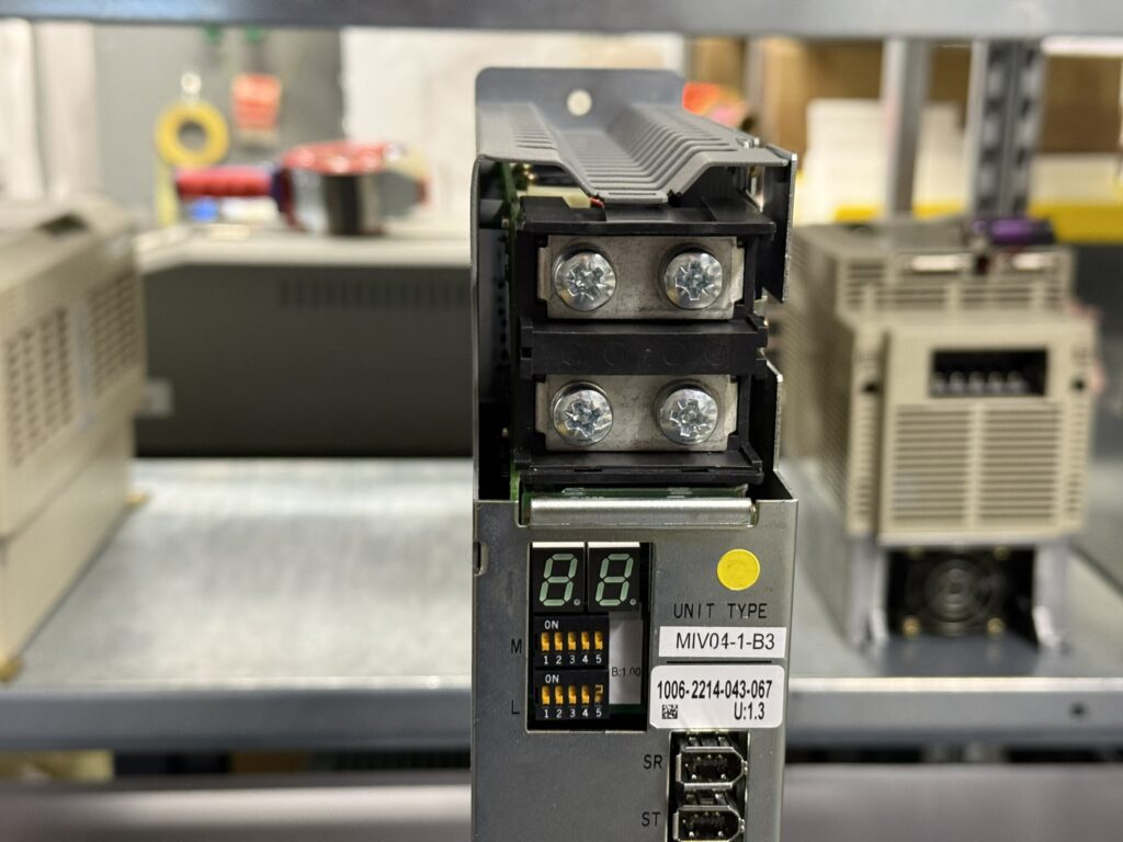
| Display | 7-segment LED |
| Encoder interface | Okuma Encoder Link |
| Communication | Servo Link to OSP control |
| Mounting | Control cabinet |
| Weight | approx. 6.0–7.0 kg |
| Dimensions | approx. 380 × 100 × 325 mm |
| Manual reference | Okuma MIV Inverter Unit Manual |
Operating Environment and Compatible Devices
The Okuma MIV04-1-B3 is a single-axis servo inverter from the MIV series and is used in Okuma CNC machine tools for precise control of linear and rotary axes. Typical applications include lathes, machining centers and special-purpose machines with OSP controls.
The drive is designed for operation with Okuma BL servo motors and PREX motors in the medium power range. Power is supplied centrally via Okuma MPS or MPR power supply units through the DC intermediate circuit.
Functional Description
The MIV04-1-B3 performs complete control of a single servo axis. It processes command values from the OSP control and regulates current, torque, speed and position of the connected motor. High-resolution feedback signals are received via the encoder link and are required for precise position control.
The power stage converts the DC intermediate circuit voltage into controlled three-phase motor currents. Integrated protection functions monitor current, temperature, supply voltages and position deviation to protect both the machine and the drive from damage.
Alarm Messages and Troubleshooting
| Alarm code | Description | Cause | Action |
|---|
| A.L. 01 | Power supply unit error | Fault in MPS or MPR supply | Check power supply |
| A.L. 03 | DC bus voltage error | Overvoltage or undervoltage in DC circuit | Check mains and supply |
| A.L. 04 | Motor power line overcurrent | Overcurrent in motor lines | Check motor, cables, drive |
| A.L. 05 | Inverter overheat | Excessive inverter temperature | Check cooling |
| A.L. 06 | Inverter overload | Continuous overload condition | Check load, mechanics, drive |
| A.L. 10 | Encoder communication error | Encoder link disturbance | Check encoder and cable |
| A.L. 20 | Motor overheat | Motor temperature too high | Check motor and environment |
| A.L. 21 | Servo link communication error | Communication fault to OSP | Check servo link |
| A.L. 28 | DIFF over | Excessive position deviation | Check control loop, mechanics, drive |
| A.L. 32 | Speed deviation too large | Speed deviation beyond limit | Check motor, encoder, drive |
Components
| Assembly | Designation | Function | Notes |
|---|
| Control board | ICB1 1-Axis | Control and communication | Check firmware and ID |
| Power board | IVPB04 or E4809-820-010-B | Power control | Thermal inspection |
| Interface board | E4809-045-209A | Signal distribution | Check connectors |
| Power module | MIV0303 | DC to AC power conversion | Check overcurrent and temperature |
| Fan | Internal | Cooling of power electronics | Check wear regularly |
Service Notes
When replacing or servicing the MIV04-1-B3, special attention must be paid to the correct setting of the axis ID using the rotary switches on the control board. An incorrect ID will lead to communication errors with the OSP control.
For units with the B3 designation, it must be ensured that firmware and servo data match the specific machine configuration. In many cases, it is recommended to transfer the original control board if it is electrically sound.
Conclusion
The Okuma MIV04-1-B3 is a robust and powerful single-axis servo drive for precise CNC applications. Due to its age and the thermal stress during continuous operation, preventive maintenance, fan replacement and regular inspections are essential to permanently avoid alarms such as A.L. 06 or A.L. 28 and to ensure long-term machine availability.