11.10.2025 by Viktor Siebert
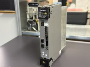
Repair of an Okuma MIV02-1-B1 Nr. 1006-2212 Servo Drive Unit with axis vibration and noise issue
The customer reported:
“When braking, the motor makes a squealing noise. Replacing it with another unit solves the problem. With the MIV02-1-B1, the Z-axis hums on startup until the control shuts down. No alarm appears on the drive.”
During testing, the unit powered up normally but behaved abnormally under load.
As soon as the axis feedback loop became active, strong mechanical resonance appeared.
Such symptoms on Okuma MIV drives typically indicate feedback loop irregularities or gate control malfunctions.
After full disassembly, the following work was carried out:
- Cleaning of dust, oil, and metal residues from cooling channels
- Inspection of all boards for discoloration and cold solder joints
- Measurement of gate signals and comparison to reference data
- Replacement of aged components in control and power circuits
- Verification of internal voltages (+5 V, ±12 V, +24 V)
After completion, the unit was tested in a full-axis setup with an OSP U100 controller and BL II motor.
The previous noise and vibration were completely eliminated.
The axis ran smoothly, with stable torque and temperature readings.
After a 6-hour endurance test, the drive was released for customer use.
Preventive Measures for the Customer
- Clean cooling ducts and fans regularly (every 6 months)
- Inspect connectors for oil and dust contamination
- Check Servo Link and encoder cables for bending or wear
- Perform regular insulation measurements between motor and power lines
- Replace fans every 2 years
- Verify grounding and potential equalization when replacing drives
- Keep a backup of servo parameter files (Servo Data File)
Conclusion
The Okuma MIV series is highly reliable but sensitive to communication or voltage fluctuations.
Regular maintenance and preventive replacement of thermally stressed components help to avoid downtime and costly failures.
For more information about our Okuma repairs, please click here.
📞 Feel free to contact us if you have any questions regarding your Mitsubishi drive technology. Our experienced team is always ready to provide you with expert advice and support.
Technical Specifications (Device Data):
| Parameter | Value |
|---|
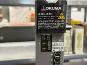
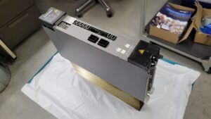
| Model designation | MIV02-1-B1 |
| Part number | 1006-2212-028-083 |
| Manufacturer | OKUMA Corporation |
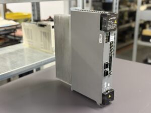
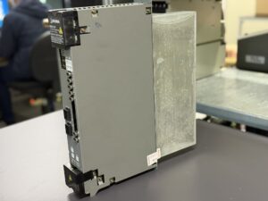
| Device type | AC Servo Drive Unit (MIV Series) |
| Rated voltage | 283–325 V DC (supplied by MPS/MPR Power Supply Unit) |
| Rated current | approx. 11 A |
| Output power | approx. 2 kVA |
| Control logic voltage | +24 V, ±12 V, +5 V |
| Cooling | Forced air cooling (top-mounted fan unit) |
| Weight | approx. 7.5 kg |
| Dimensions (H×W×D) | approx. 330 × 90 × 250 mm |
| Insulation class | B |
| Protection class | IP20 |
| Compatible controllers | OKUMA OSP U / E / P / U10 / U100 |
| Manual reference | Okuma Inverter Unit (MIV) Manual 4742-E P-17 ff. |
Operating Environment & Compatible Equipment
The MIV02-1-B1 is used in OKUMA CNC machines, typically in combination with OSP U or P controllers.
Typical applications:
- Axis control in vertical and horizontal machining centers (e.g., MX-45VAE, LB15II, MA-400HA)
- Operation of VAC or BL servo motors (e.g., VAC II 5/7.5, BL II D series)
- Communication via Servo Link (optical data transmission)
- Power supplied through MPS/MPR-35 or 40 Power Supply Units
The drive is designed for ambient temperatures between 0–45 °C and humidity up to 85% RH (non-condensing).
Functional Description
The MIV02-1-B1 is an inverter module used for servo motor control.
It converts the DC voltage from the MPS/MPR power supply into three-phase AC voltage, supplying the motor with precise variable frequency and amplitude.
Control signals are transmitted via the Servo Link system (L and M side).
A 7-segment LED display indicates operation, warnings, and alarm states.
Internal voltages (+24 V, ±12 V, +5 V) are continuously monitored.
The MIV drive performs torque, speed, and position control based on feedback from magnetic or optical encoders.
Key protection features include:
- Overcurrent, overvoltage, and overtemperature protection
- Motor and inverter overload protection
- Watchdog and CPU supervision
- Communication monitoring (Servo Link, Encoder Link)
Alarm Messages & Troubleshooting
| Code | Error Description | Cause | Solution |
|---|
| 01 | Power Supply Unit Error | Voltage loss or power supply failure | Check input voltage, replace MPS/MPR unit if necessary |
| 03 | DC Bus Voltage Error | DC bus voltage too high or too low | Check supply voltage, replace MIV or MPS/MPR unit |
| 04 | Motor Power Line Overcurrent | Overcurrent in motor circuit | Inspect motor and inverter for short circuit |
| 05 | Inverter Overheat | Inverter temperature too high | Check fan and ambient cooling |
| 06 | Inverter Overload | Load exceeds specification | Reduce cutting torque, check MIV condition |
| 10 | Encoder Communication Error | Encoder communication failure | Check encoder cable and connectors |
| 12 | Encoder Initialization Error | Encoder initialization failed | Replace encoder or communication cable |
| 17 | Magnetic Encoder Error | Signal fault from magnetic encoder | Check encoder or cable, verify Servo Data File |
| 20 | Motor Overheat | Excessive temperature at motor or encoder | Check thermal sensor and cooling airflow |
| 21 | Servo Link Communication Error | Communication failure with NC | Inspect Servo Link cable and FCP board |
| 28 | DIFF Over | Excessive position deviation | Inspect mechanics, test MIV and motor |
| 32 | Speed Deviation Too Large | Deviation between commanded and actual speed | Check load torque, replace MIV if required |
| 33 | Collision Detection | Axis collision or mechanical blockage | Check mechanics, adjust NC torque limiter |
| 34 | Emergency Stop Time Over | Machine failed to stop within preset time | Check braking parameters and servo data file |
Components
| Assembly | Designation / Code | Function |
|---|
| Control board | ICB1 / E4809-770-107-F / 1006-2101 | Central logic and communication control |
| Power board | IVPB02 | Power transistor and PWM stage |
| Connection board | E4809-045-209A | Links control and power sections |
| Power module | MIV0303 | Main inverter module, energy and current path |