14.09.2025 by Viktor Siebert
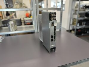
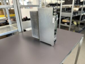
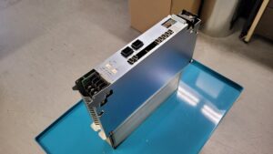
Okuma MIV01-1-B1 Servo Drive Unit + Technical Analysis and Repair Practice
When the unit arrived at our facility, the customer had already described the symptoms in detail. The axis motor vibrated so strongly that the entire machine shook. Surface finish was poor, positioning lost accuracy, and even rapid traverse was unstable. In the shop, the suspicion fell on the motor. A new BL motor was ordered from Okuma, installed, and measured. But the behavior remained unchanged.
This uncertainty unsettled the customer. Okuma offered an exchange unit at high cost, but without a clear guarantee of success. The offer exceeded 4000 Euro. Still seeking clarity, the customer discussed alternatives with a business partner, who recommended sending the drive to us for inspection.
Following our established procedure, we first reproduced the error under controlled conditions. Our Okuma test machine allows the MIV01-1-B1 to be operated with matching DC supply and encoder link exactly as in the customer’s environment. The abnormal behavior was immediately visible: the axis started, but did not reach a stable control state. Instead, it oscillated at low speed and shook violently under load.
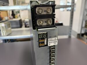
The 7-segment display did not show a hard fault at first – a typical situation with degraded drive stages. Not every control instability immediately triggers an alarm. Therefore, we followed our checklist step by step: exclude mechanical issues, verify power supply, check Servo Link communication, check Encoder Link, monitor the DC bus. Everything appeared stable. The focus then shifted to the power stage and gate drive section.
The MIV01-1-B1 is a robust unit. Nevertheless, we repeatedly observe age-related weaknesses in the field. High thermal cycles stress semiconductors and electrolytic capacitors. If fans or airflow are restricted due to dust and contamination, component temperatures rise significantly. This reduces reliability reserves. In this case, the gate drive circuit showed degraded components. The power module itself already had latent damage. Under certain load conditions, phase currents became unbalanced. This explains the oscillation and vibration without immediate shutdown.
We decided on a full overhaul according to our internal standards. The process included:
- Cleaning of the entire unit, removal of dust, oil and residues,
- Replacement of the power transistor module,
- Renewal of DC link capacitors with high-quality parts,
- Refurbishment of the gate drive circuits and recalibration,
- Reworking of solder joints where microscopic cracks were found,
- Inspection of current measurement circuits to ensure reliable feedback.
After rebuild, we proceeded with function verification on the test machine. First under no load, then under progressively increasing profiles. Defined thermal cycles ensured the unit was also stressed at high temperature. The axis now ran smoothly. No vibrations, no oscillations. The 7-segment display showed proper transition through the startup phases and stable operating states.
We extended testing into endurance runs, simulating different feed profiles and provoking short torque peaks. In all cases, the regulation loop remained quiet and stable.
Each step was documented in our checklists and test protocols. This documentation is essential, not a formality – it ensures repeatability and transparency.
The unit was returned to the customer together with the full test report. Once reinstalled, the machine regained full accuracy and surface quality. Production was back to normal.
Lesson learned: not every vibration is caused by the motor. Especially in older drives, the combination of thermal aging and reduced cooling capacity is a frequent root cause for unstable control. Early intervention saves downtime and prevents collateral damage.
Preventive Measures for the Customer
- Regularly clean electrical cabinets and ensure free airflow
- Inspect and replace fans early – spare part numbers are listed in the OEM manual
Conclusion
The 1.0 kW axis in this case clearly showed how sensitive servo loops react to aging components in the power stage. With a structured overhaul, the drive regained full stability. Regular preventive care extends lifetime and protects the machine from secondary failures.
Technical Specifications
| Parameter | Value |
|---|
| Unit type | Okuma MIV01-1-B1 single-axis inverter for BL motors |
| Part number | 1006-2211 |
| Axis power in this case | 1.0 kW |
| Typical motor range according to OEM combinations | 0.75 kW to approx. 1.8 kW with BL motors of the MC series |
Note on classification
The table reflects the 1.0 kW axis of this particular case. The dimensions and weight originate from the OEM data for the MIV01-1 size and are valid independent of the exact motor rating.
Application Environment and Compatible Equipment
The MIV01-1-B1 is used in Okuma lathes and machining centers as feed axis drive. It is connected to the OSP control via the Servo Link and powered by the DC supply modules MPS or MPR, which provide 300 V DC and 24 V DC. Typical combinations are with BL motors in the range 0.75 to approx. 1.8 kW.
Alarm Messages and Troubleshooting
| Alarm | Description | Cause | Solution |
|---|
| 01 | Power Supply Unit Error | Fault in MPS/MPR supply or voltage monitoring | Check supply, replace MPS/MPR, replace drive if required |
| 03 | Inverter DC Bus Voltage Error | DC bus voltage too high or too low | Check supply, check MIV and MPS/MPR |
| 04 | Motor Power Line Overcurrent | Overcurrent through motor line | Inspect motor, cabling, drive |
| 05 | Inverter Overheat | Excessive internal temperature | Check fans, cooling, ambient |
| 06 | Inverter Overload | Continuous overload condition | Reduce load, check parameters, inspect drive |
| 07 | Commercial Power Source Error | Supply voltage abnormal | Check mains quality, cable length/cross section |
| 10 | Encoder Communication Error | Communication error in encoder link | Check encoder, cables, drive |
| 11 | Encoder Error | No valid position data | Replace motor encoder, check cabling |
| 12 | Encoder Initialization Error | Initialization failed | Inspect encoder cabling and parameters |
| 20 | Motor Overheat | Excessive temperature in motor/encoder | Check motor, cooling, encoder |
| 21 | Servo Link Communication Error | OSP control ↔ drive communication fault | Inspect Servo Link cables, FCP board, drive |
Components
| Type | Board/Module | Qty |
|---|
| Control board | ICB1 or E4809-770-107-F | 1 |
| Power board | IVPB01 | 1 |
| Link board | E4809-045-209A | 1 |
| Power module | MIV0303 | 1 |