29.03.2026 by Viktor Siebert
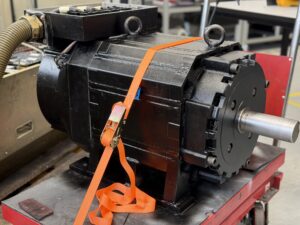
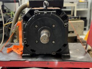
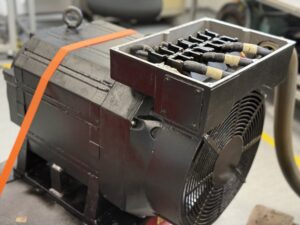
Okuma AC Spindle Motor VAC-YMM45/37R-112 Repair After Overload Caused by Seized Rear Bearing
Initial situation and fault pattern.
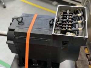
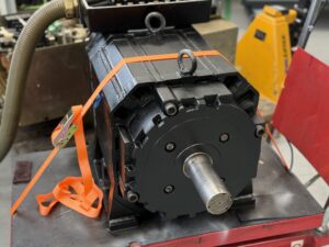
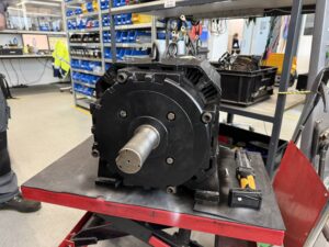
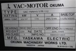
This repair case involved an Okuma AC spindle motor VAC-YMM45/37R-112, used together with an Okuma VAC II Drive Unit D45-A or 1006-1262. According to the nameplate, this is a spindle motor rated at 45 kW in 30 minute duty and 37 kW in continuous duty, with 170 V motor voltage, 291 A or 248 A, and a speed range of 1125 to 4500 min⁻¹. The year of manufacture according to the nameplate is June 1999. The motor is equipped with a Sanyo Denki 101-7801-04 resolver feedback unit. The VAC II documentation shows that this drive combination works with resolver feedback, motor overload signal, motor cooling and protective functions. The connection between drive and motor includes power connections, resolver, thermal protection and fan supply.
The fault pattern was initially typical of a progressing mechanical failure, but not immediately clear, because the motor continued to run despite already noticeable noise. According to the customer, the spindle kept running until shortly before failure, but with clearly loud running noise. After that, the drive reported overload and the motor no longer turned. What was technically important here was that the mechanical load had already been removed. The belt was taken off, so the motor was running without load. Even then, the rotor could no longer be moved. This exact point is decisive for fault isolation. If a motor remains blocked even without a coupled load, the cause is generally inside the motor itself and no longer in the driven assembly.
Before opening or disconnecting plugs, always isolate from power, secure against restart, wait for discharge time and verify absence of voltage. Measurements on live parts may only be carried out by a qualified electrician with suitable equipment and according to local rules.
Incoming inspection and first diagnosis
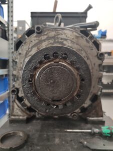
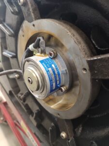
During incoming inspection, the external condition was checked first. The nameplate was fully legible, so the assignment to motor and spindle drive was clearly identified. The blocked rotor condition could be confirmed immediately. Even by hand, no free movement was possible. This made it clear at an early stage that the issue was not only an electrical secondary fault, but a major mechanical defect inside the unit.
In the next step, the feedback system was examined. In cases like this, the resolver can often also be affected by vibration, heat or secondary damage, so it was checked for mechanical damage, play, rubbing marks and cable condition. In this case, the resolver did not appear to be the primary cause of the fault. That also matches the field behavior. As long as a resolver still delivers stable feedback signals, the drive initially reacts correctly to the rising load with increasing current and finally with overload protection. That is exactly what the customer described.
The first technical assessment was therefore: no primary feedback fault, but a mechanically seizing unit with a resulting overload message in the drive. This is also plausible in connection with the VAC II protection logic. The documentation lists motor overload, resolver related faults, overcurrent and power circuit alarms as typical protective and shutdown conditions.
Technical analysis
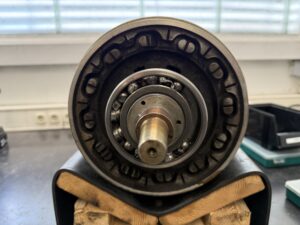
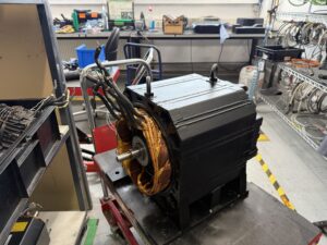
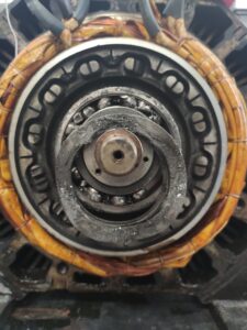
After disassembly, the actual cause became clear. The rear ball bearing was massively damaged. A large part of the rolling elements had been clearly ground down, and the bearing cage had deformed and jammed. As a result, the bearing could no longer perform its function. Instead of proper guidance, there was initially increased friction, then increasing running noise, followed by temperature rise and finally mechanical blocking of the rotor.
The cause effect chain was very clear in this case. Progressive bearing wear led to increasingly poor guidance of the rotor shaft. This increased running noise, friction torque and mechanical instability. In the final stage, the bearing geometry collapsed to the point where parts of the bearing guidance jammed. The rotor no longer turned freely. The drive still attempted to regulate, but only saw sharply rising load current or missing acceleration. The result was the overload message.
Why the motor still ran until shortly before failure can be technically explained quite well. As long as a bearing is severely damaged but not yet completely jammed, the motor can continue to run with increased current and clear noise. Only when the cage collapses or the rolling elements tilt does the fault change from increased friction into true mechanical blockage. Exactly this transition is often the point in practice where the operator first sees an alarm.
Electrically, this case was interesting because the drive was not the cause, but the protective instance. The feedback was still sufficient for regulation, but the protection logic intervened because of the mechanical resistance. That is generally consistent with the overload and fault patterns documented in the VAC II manual around motor overload, excessive vibration and noise, and commanded speed cannot be obtained.
Repair measures and overhaul
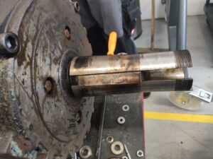
During the repair process, the motor was completely disassembled and technically cleaned. All functionally relevant assemblies were checked for secondary damage. The damaged bearing arrangement was fully renewed. Special attention was paid to the bearing seats, the rotor shaft, the mating surfaces and the free movement of the rotor. With such a severe bearing failure, a simple bearing replacement is only sufficient if no consequential damage has occurred on the surrounding functional surfaces. Accordingly, the work involved not only replacement, but also geometric and mechanical inspection.
The feedback system was also checked, because strong bearing noise and vibration often affect signal quality. In this case, the resolver was functionally checked as well and observed for stable signal behavior after reassembly. The basic electrical test of the motor showed no noticeable insulation weakness in the workshop process. This meant that nothing stood in the way of a repair based on the mechanical root cause.
As a preventive measure, the overall motor condition in the areas of bearing system, running behavior and thermal capability was assessed. For drives of this age, it makes sense during such an overhaul not only to eliminate the immediate defect, but also to assess adjacent wear points. Especially in spindle motors with high speed and long operating hours, the mechanical condition of the bearing system is the key factor for noise, runout, feedback stability and load on the drive.
Final function test
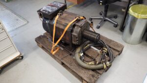
After reassembly, the motor was operated on the test bench with the matching Okuma VAC II spindle drive. The test included on and off behavior, enable function, smooth startup, operation at low speed, medium speed and high speed, as well as observation of running noise, current draw, feedback and thermal behavior.
In this case, the direct comparison with the fault pattern was especially important. Before the repair, the rotor was mechanically blocked. After the repair, the motor had to start freely again, accelerate cleanly and run across the speed range without noticeable noise peaks. That is exactly what was achieved in the test run. The resolver feedback also showed stable behavior. During the test, there were no signs of dropouts, unstable speed control or renewed overload reactions. The motor ran successfully and was tested on the Okuma VAC II Drive.
Conclusion
The actual damage in this case was clearly located in the mechanical bearing system of the motor and not primarily in the drive or the feedback. That makes the case technically clear, but often difficult in the field, because the drive continues working until shortly before standstill and the first visible sign often appears only as an overload alarm. Through complete disassembly, proper mechanical overhaul and the subsequent test on the matching spindle drive, the repair is technically sustainable. The drive was not only made able to rotate again, but also functionally verified under realistic conditions.
Price and Delivery Time for Okuma VAC-YMM45/37R-112 AC Spindle Motor
For more information about our Okuma repairs, please click here.
📞 Feel free to contact us if you have any questions regarding your Mitsubishi drive technology. Our experienced team is always ready to provide you with expert advice and support.
Technical Specifications
| Field | Motor |
|---|
| Manufacturer | Yaskawa Electric / Okuma |
| Device type | AC spindle motor |
| Model designation | VAC-YMM45/37R-112 |
| Series | Okuma VAC Motor |
| Power | 45 kW / 37 kW |
| Input voltage | not applicable, speed controlled via spindle drive |
| Output voltage | 170 V |
| Rated current | 291 A / 248 A |
| Control type | speed controlled spindle drive with resolver feedback |
| Feedback | Resolver Sanyo Denki 101-7801-04 |
| Cooling | spindle type forced or external cooling on motor side, system dependent |
| Protection class | approx. industrial built in motor, exact protection class not stated on the nameplate |
| Ambient temperature | approx. 0 to 40 °C with clean cooling air |
| Mounting | flange mounting |
| Origin | Nagoya, Japan |
| Product status | existing equipment, older system |
| Field | Drive |
|---|
| Manufacturer | Okuma |
| Device type | VAC II Drive Unit |
| Model designation | D45-A / 1006-1262 |
| Series | VAC II |
| Power | matching the 45/37 kW spindle motor, exact frame size not clearly verifiable from the available manual |
| Input voltage | 3~ 200 to 230 VAC, depending on VAC II version described in the manual |
| Output voltage | variable motor output voltage matching the spindle motor |
| Rated current | approx. matching the motor axis, not clearly derivable from the available drive document |
| Control type | transistorized VAC spindle drive with resolver evaluation |
| Feedback | resolver, overload signal, thermal protection, fan supply according to VAC II connection diagrams |
| Cooling | fan cooled power module |
| Protection class | control cabinet unit |
| Ambient temperature | typical control cabinet operation, ensure sufficient cooling |
| Mounting | vertical control cabinet mounting |
| Origin | Japan |
| Product status | existing equipment, older system |
The motor values come directly from the nameplate. The VAC II documentation describes structure, connection diagrams, protection logic and alarm display of the spindle drive.
Operating environment and possible applications
Typical machines
CNC lathes and machining centers with Okuma spindle technology
Typical years of manufacture
Motor year of manufacture here 1999, VAC II documentation 1st Edition March 1990, therefore typical for older existing systems and retrofit cases.
Typical applications
Main spindle operation, acceleration and braking of tool spindles, speed controlled machining operation
Requirements for environment and control cabinet
Clean cooling air, stable power supply, secure grounding, shielded signal routing and robust power wiring. The VAC II documentation points to correct power supply, connectors, fans and secure terminal connections.
Notes on thermal and electrical load
Bearing damage significantly increases current demand and thermal stress. Mechanical stiffness, imbalance and deteriorated runout directly affect current consumption, control dynamics and protective shutdowns.
Functional description
Basic function
The spindle drive generates a controlled motor output from the mains supply for the AC spindle motor. The motor converts this electrical power into torque and speed.
Interaction of power section, control and feedback
The power section supplies the motor with variable voltage and current. The control compares setpoint and feedback. Feedback is provided by the resolver. According to the VAC II connection diagrams, thermal protection, overload signal and fan connections are also part of the overall system.
Enable
The drive enables the motor after correct supply and enable logic. In the event of a fault, it shuts down or reduces output.
Protection logic
Typical protective functions are overcurrent, overvoltage, undervoltage, phase loss, resolver fault, motor overload and heat sink overheat. The VAC II documentation lists these faults both as LED codes and in the alarm table.
Thermal monitoring
Motor and drive are thermally monitored. Overload caused by mechanical damage can therefore be detected early and converted into a protective shutdown.
Signal monitoring
The feedback is monitored for plausibility, signal loss and control deviation. Resolver faults, communication faults and loop errors are documented in the VAC II manual.
Why these functions are safety relevant
Without this monitoring, a blocked motor could continue to be energized, which would severely damage winding, power section and mechanics. Especially in high power spindle drives, the protection chain is critical.
Alarm messages and troubleshooting
| Alarm code | Description | Possible cause | Recommended measure |
|---|
| RES | Resolver alarm | faulty feedback, implausible resolver signal | check resolver, cables and plug connection |
| AD | A/D access alarm | fault in signal conditioning or electronics | check control PCB, repair if necessary |
| PAR | RAM parity error | memory or control logic faulty | check electronic assembly |
| ACC | Microcomputer access error | fault in internal processing | check control assembly |
| LOOP | INT6 loop error | internal control fault | check drive electronics |
| WDOG | Watch dog error | CPU or monitoring fault | check electronics, replace if necessary |
| IOCM | Motor cable overcurrent | short circuit or severe load jump in the motor branch | check motor cable, motor and insulation |
| IOCS | Inverter bridge short circuit | power section damaged | check power section |
| IOCR | Regeneration unit power transistor short | fault in regeneration unit | check regeneration circuit |
| OV | Power circuit overvoltage | DC link voltage too high, regeneration problem | check supply and regeneration |
| UV | Power input undervoltage | supply too low | check mains voltage and incoming supply |
| PH | Phase open | phase loss | check supply and wiring |
| LOSS | Loss of power supply at calculation circuit | control supply missing | check power supply and connectors |
| OS | Over speed | faulty feedback or uncontrolled motor acceleration | check resolver and control |
| READ | Velocity command read error | faulty setpoint signal | check setpoint path |
| SVP | Power circuit undervoltage | undervoltage in the power section | check incoming supply and power unit |
| RAER | RAM faulty error | memory fault | check electronics |
| DSE | DIP switch setting error | unsuitable parameter setting | check switches and device software |
| DSC | Excessive velocity deviation error | large deviation between setpoint and actual value | check mechanics, motor and feedback |
| WCHER | Winding changeover error | changeover faulty | check magnetic switch and changeover |
| OH | Heat sink overheat | insufficient cooling | check fan and airflow |
| OL | Motor overload | mechanical stiffness, overload, cooling problem | check mechanics, bearing system, fan and load |
The entries are based on the VAC II alarm display and fault table in the manual.
Assembly overview
| Assembly | Functional designation | Function | Notes for inspection or repair |
|---|
| Stator rotor unit | power generating motor unit | generates torque and speed | check for rubbing marks, heat marks and free movement |
| Front and rear bearing system | shaft guidance | supports rotor and ensures runout | check for noise, play, smooth running and consequential damage |
| Feedback system | resolver | provides actual value for control | check signal stability, cables and mechanical seating |
| Thermal protection | temperature monitoring | protects motor against overheating | check continuity and plausibility |
| Fan circuit | motor cooling | thermal stability under load | check supply, operation and airflow |
| Power section in drive | output stage | supplies motor with controlled power | only inspect after excluding mechanical root cause |
| Control assembly | drive control | setpoint processing and protection logic | in case of secondary faults, review alarm history |
| Power connections | motor wiring | transmits motor output power | check contacts, insulation and terminals |
| Signal connections | feedback and protection signals | control and condition monitoring | check shielding and plug seating |