13.03.2026 by Viktor Siebert
Mitsubishi MDS-DH2-V2-8080 servo drive with no response, frozen LED display, and excessively loud fan operation
Initial situation and fault symptom.
A Mitsubishi Servo Drive Unit MDS-DH2-V2-8080 from a CNC drive environment was delivered. During the functional test, the unit showed no expected response. The front LED display appeared frozen, without a plausible change of status or message. At the same time, the fan ran noticeably loud and uneven. The symptom occurred already during the power up attempt, independent of load demand or axis motion. Technically, the combination of a static display and clearly increased noise in the cooling circuit was unusual, because both often indicate disturbed internal supply and faulty monitoring.
Incoming inspection and first diagnosis
During incoming inspection, a visual check of the housing, connectors, ventilation channels, and contamination level was performed first. The fan area was clearly contaminated. Reproducibility was then checked on the test bench. The behavior was stably reproducible. No clean initialization, LED display without dynamic sequence, fan permanently loud. As a first narrowing step, the internal supplies and their stability were assessed, as well as the control of the cooling circuit. Measurements on live parts are carried out exclusively by qualified electricians with suitable equipment and according to local rules. Before opening or unplugging connectors, always apply: switch off to a de energized state, secure against reconnection, wait for discharge time, verify absence of voltage.
Technical analysis
In this series, the internal supply is critical for logic, display, enable, and protective functions. A mechanically loaded or contaminated fan not only increases current demand, but can also drive the fan control into a limit range. A faulty or overloaded fan control then loads the internal power supply sections, which leads to unstable or incorrect auxiliary voltages. If auxiliary voltages are not clean, the control can hang, displays can freeze, and monitoring can react implausibly. As a result, power functions are also affected negatively, because the power electronics depend on correct supplies, correct drive signals, and stable protection thresholds.
In this unit, a clear cause effect chain was found: contamination in the fan area caused increased mechanical load, resulting in increased electrical load of the fan drive, which led to overload or malfunction in the internal power supply area. The resulting incorrect or unstable voltages propagated toward the power stage, where early stage defects were already visible. This pattern is typical for older or thermally stressed servo drives, especially when maintenance intervals for filters and fans are not observed or when the cabinet is continuously operated at the temperature limit.
Repair actions and restoration
The restoration was carried out foreseeably as a preventive overhaul, because a pure partial repair can lead to short term follow up failures when pre damage is evident. First, the cooling circuit was restored, including cleaning and re establishing stable fan control. Afterwards, the internal supply area was repaired and stabilized so that all auxiliary voltages are again within expected tolerances. Then the power level was reworked to eliminate pre damage caused by incorrect voltages.
As a preventive standard, all typical wear and consumption areas in the drive were overhauled, and power critical semiconductor functions within the end stage were evaluated and, where early stage indications existed, renewed or secured. This prevents another weakened area from failing after a short runtime and making repair necessary again. In addition, connectors were checked, airflow guidance was verified, and recommendations for maintenance and environment were derived.
Final functional test
The functional test was performed on the workshop test bench with regulated supply, suitable measuring equipment, and a practice oriented load simulation. Tested items included power on and off behavior, initialization, enable, control stability, and protection functions. Operation was checked in several states, including low speeds and longer holding phases, because thermal effects and control deviations are especially visible there. In addition, overcurrent and temperature monitoring as well as feedback signal monitoring were verified. Result: the unit initializes reproducibly, the display behaves plausibly, the fan runs smoothly within normal noise limits, and operation remains stable without abnormal reactions.
Conclusion
The failure was not a single isolated defect, but a chain reaction of contaminated cooling, overloaded fan control, disturbed internal supply, and resulting pre damage in the power level. The sustainable solution consisted of a preventive overhaul with supply stabilization and restoration of a robust cooling function, complemented by elimination of early stage defects in power critical areas. This makes the repair not only functional in the short term, but also suitable for continuous operation under real cabinet conditions.
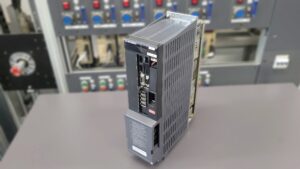

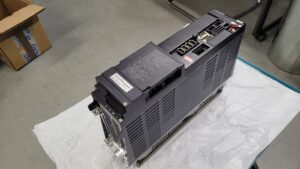
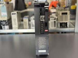
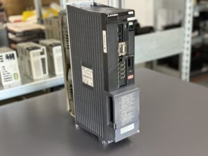
To mentioned Mitsubishi Drive: Mitsubishi MDS-DH2-V2-8080 Servo Drive Unit
More details about our Mitsubishi repair services can be found here:
Mitsubishi drive Repair by Industrypart
📞 Feel free to contact us with any questions about your Mitsubishi drive technology.
Our expert team is happy to help!
Technical specifications
| Field | Value |
|---|
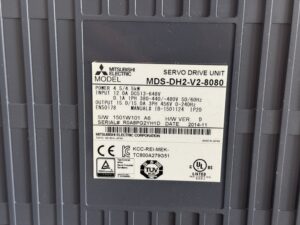
| Manufacturer | Mitsubishi Electric |
| Device type | Servo Drive Unit |
| Model designation | MDS-DH2-V2-8080 |
| Series | MDS-DH2 (MDS-D/DH environment) |
| Power | 4.5 / 4.5 kW |
| Input voltage | DC link 513 to 648 V, control section approx. 1~ 380 to 480 V 50/60 Hz |
| Output voltage | 3~ approx. 456 V, 0 to 240 Hz |
| Rated current | 15.0 / 15.0 A |
| Control type | Digital servo controller for CNC axis drives |
| Feedback | Feedback via detector interfaces, incremental or absolute depending on system, approx. |
| Cooling | Forced air cooling with controlled fan |
| Protection class | IP20 |
| Ambient temperature | approx. 0 to 55 °C in control cabinet, depending on derating, approx. |
| Mounting | Control cabinet mounting, vertical installation with free air channel, approx. |
| Origin | Japan |
| Product status | unknown, typically legacy in existing systems |
Operating environment and typical applications
Typical operating environments are CNC machine tools, machining centers, lathes, automation axes, and handling systems. Typical installation years are often in the range of approx. 2005 to 2015, depending on machine builder and retrofit history. Applications range from positioning axes to continuous feeds, often with high dynamics and changing load profiles.
Key factors are clean cabinet airflow, working filters, sufficient heat removal, and stable supply conditions. Continuous thermal stress, high ambient temperatures, and clogged fans accelerate aging. Electrically critical are fluctuating supply, aged power supplies in the system, and poor grounding or shielding, because these can impair internal monitoring and feedback signals.
Functional description
The unit converts DC link energy into controlled three phase motor currents and controls torque, speed, and position via feedback. For this, a control and logic section, the power level, and the feedback interfaces work together. Enable is only granted with plausible auxiliary voltages, valid feedback, and error free protection checks.
Protection logic monitors, among other things, undervoltage and overvoltage in the DC link, overcurrent, overtemperature, feedback faults, and internal processing faults. These functions are safety relevant because they must decelerate or switch off the motor in a controlled way in case of faults to prevent uncontrolled motion, thermal damage, or secondary damage to the machine and peripherals.
Alarm messages and troubleshooting
| Alarm code | Description | Possible cause | Recommended action |
|---|
| 10 | Undervoltage DC link detected | Unstable supply, weak system power supply, high inrush | Check supply, check DC link, evaluate power supply and wiring |
| 11 | Axis selection incorrect | Switch setting or parameterization implausible | Check axis assignment, compare parameters with documentation |
| 12 | Memory error during self check | Internal hardware self check failed | Do not continue operation, professional diagnosis and repair |
| 13 | Software processing error | Unstable auxiliary voltages, disturbance in control logic | Check auxiliary voltages, identify causes for reset or freeze |
| 16 | Magnetic pole position detection error | Feedback or initialization not plausible, absolute setup missing | Check feedback setup, verify parameters and initialization logic |
| 17 | A/D converter current feedback error | Feedback implausible, disturbance in measurement path | Check measurement paths, verify wiring and shielding |
| 24 | Ground fault detected | Insulation fault motor or cable, moisture, shield contact issue | Insulation test by qualified electrician, check cable and motor |
| 25 | Absolute position data lost | Battery or data retention faulty, feedback issue | Check data retention, perform reference run and feedback test |
| 31 | Overspeed | Feedback faulty, unstable control, wrong parameters | Check feedback, validate parameters, check mechanics for free movement |
| 33 | Overvoltage DC link | Regeneration, braking resistor issue, supply too high | Check brake circuit, evaluate supply, review load profiles |
| 3A | Overcurrent | Short circuit, mechanics blocked, power level disturbed | Check load side, evaluate motor and cable, professional unit test |
| 3B | Power module overtemperature | Cooling insufficient, fan or airflow disturbed | Clean airflow, check filters and fan, reduce cabinet temperature |
| 3C | Regeneration circuit error | Braking function disturbed, thermal overload, circuit fault | Check brake circuit, verify resistor and wiring |
Module overview
| Module | Functional designation | Function | Notes for testing or repair |
|---|
| Control board | RM120C-22 X or BC886A159G51 | Responsible for logic, signal processing, enable control, internal monitoring, and sequence management | Check supply stability, reset behavior, communication paths, and connectors. If the display freezes, particular attention must be given to stable auxiliary voltage supply. |
| Power board | RM162C-V2 or BC886A010G52 F | Responsible for driving the power stage and monitoring current and voltage signals | Check measurement paths, driver sections, thermally stressed areas, and possible effects caused by incorrect internal voltages. |
| Power section | BKO-NC1207 H84 or A2-DH2-V2-8080 | Performs the power conversion for motor supply, manages energy flow, and executes protective shutdown | Check DC link behavior, thermal load condition, and possible early-stage damage in the output stage caused by unstable supply conditions. |