27.02.2026 by Viktor Siebert
Mitsubishi Servo Drive Unit MDS-C1-V2-7045, Alarm 32 (overcurrent) after previous repair
Initial situation and fault symptoms.
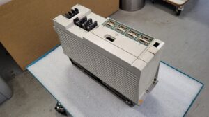
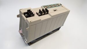
The Mitsubishi Servo Drive Unit MDS-C1-V2-7045 arrived at the workshop as a unit that had already been repaired previously. According to the customer information, a power module had already been replaced beforehand. The machine then ran for only about one day, after which the fault occurred again. On the test bench, alarm 32 appeared immediately after power on or directly when enabling the drive. The fault was reproducible, stable operation was not possible.
Technically, the rapid recurrence after a previous repair was notable. This often indicates that not only a single power stage defect is present, but also a cause in the environment, in the cooling system, or in the power stage control and monitoring.
Incoming inspection and initial diagnosis
Before any work, the safety sequence applied: switch off, secure against being switched on again, wait for the discharge time and verify the absence of voltage. Measurements on live parts are carried out only by qualified electricians with suitable equipment and according to local rules.
The visual inspection showed deposits in the air path and unreliable ventilation. Connectors and contact points were checked for tight fit and thermal traces. After that, the fault pattern was reproduced on the test bench and the load side was separated. The motor cable and power outputs were checked for short circuit and insulation faults in a de energized state, and the supply and protective earth connection were also assessed. The alarm remained reproducible even without a connected motor load, so an internal fault was the focus.
Technical analysis
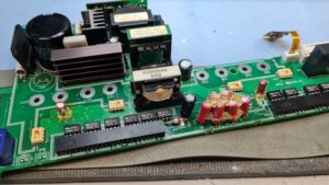
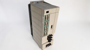
The MDS-C1-V2-7045 converts a DC intermediate circuit voltage into a three phase motor supply and monitors the motor current in fast control loops. Feedback from the motor encoder, CNC communication and temperature and current monitoring are integrated into the protection concept.
In Mitsubishi MDS troubleshooting documentation of the MDS-D/DH family, alarm 32 is described as a trip of the overcurrent protection function in the power module. As initial checks, it is stated among other things to disconnect the motor leads and check for short circuit, as well as to measure the motor insulation against earth.
The analysis here showed two coupled faults. The power stage was defective, and at the same time the control of the power stage was faulty. A replacement of the power stage alone would therefore not have helped sustainably. A combination of contamination and disturbed cooling was identified as the cause. Deposits and a defective fan led to increased temperature, which degraded electrical stability and signal quality, ultimately resulting in alarm 32 as a protective shutdown.
Repair measures and refurbishment
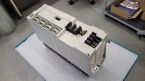
The refurbishment was carried out consistently at assembly level. The defective power stage and the associated control and monitoring unit were reworked or replaced. The unit was cleaned to remove conductive deposits and to restore insulation distances. The cooling system was repaired, the fan was replaced and the air path was checked.
In addition, power terminals, connectors and the protective earth routing were checked to avoid contact resistances and local heating. Finally, a functional check of the protection chains was carried out, in particular temperature and current monitoring.
Final functional test
The functional test was carried out on the test bench with a suitable supply for the intermediate circuit and control. Testing under load was performed for approx. two hours. The procedure included speed ramps from low speeds up to the upper operating range, repeated enabling and disabling of the drive and on and off behavior over several cycles. Thermal stability was monitored during this.
No alarms occurred during the entire test. Current consumption, control behavior and temperature curve remained normal and reproducible.
Conclusion
Alarm 32 is a protective shutdown that indicates an overcurrent situation in the power stage. In this case, the cause was not only in the power stage, but also in the control, triggered by contamination and insufficient cooling. Through the combined refurbishment of the affected assemblies and restoration of cooling, the unit was stabilized and confirmed as fault free in the load test.
To mentioned Mitsubishi Drive: Mitsubishi MDS-C1-V2-7045 Servo Drive Unit
More details about our Mitsubishi repair services can be found here:
Mitsubishi drive Repair by Industrypart
📞 Feel free to contact us with any questions about your Mitsubishi drive technology.
Our expert team is happy to help!
Technical specifications
| Field | Value |
|---|
| Manufacturer | Mitsubishi Electric |
| Device type | Servo Drive Unit, CNC servo amplifier, approx. |
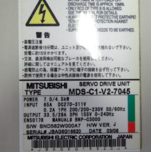
| Model designation | MDS-C1-V2-7045 |
| Series | Servo Drive, MDS-C1 family, approx. |
| Power | 7,0 / 4,5 kW (according to the nameplate) |
| Input voltage | DC 270 to 311 V (power supply), 1~ 200 V or 200 to 230 V, 50/60 Hz (control) |
| Output voltage | 3~ 155 V, 0 to 240 Hz (according to the nameplate) |
| Rated current | Input 65 A DC, output 33,5 / 28 A (according to the nameplate) |
| Control type | Digital current, speed and position control via CNC, approx. |
| Feedback | Motor encoder feedback, depending on system incremental or serial, optional machine measuring system, approx. |
| Cooling | Forced ventilation with internal fan, approx. |
| Protection class | IP20 (cabinet mounted unit), approx. |
| Ambient temperature | approx. 0 to 55 °C (depending on installation and airflow) |
| Mounting | Vertical cabinet mounting on back panel, approx. |
| Origin | Japan (manufacturer statement on nameplate) |
| Product status | probably discontinued, spare parts and service depend on machine builder, approx. |
| Standard | EN50178 (according to the nameplate) |
| Documentation | Manual No. BNP-C3000 (according to the nameplate) |
| Date code | 03/06 (according to the nameplate) |
Operating environment and possible uses
Servo amplifiers in this power class are typically used in CNC machine tools and automation systems. Common applications are feed axes, handling axes and depending on the machine concept also spindle related drives with a separate power level. The nameplate date code 03/06 indicates typical build years in the 2000s.
For operation, a clean control cabinet with defined airflow is important. Deposits in filter mats and air ducts increase the temperature in the power stage and shorten service life. Equally critical are a clean PE connection, short motor cables with correct shielding and a stable supply voltage without major dips or harmonics. With high cycle rates or frequent braking, the thermal load also increases due to regenerative energy.
Functional description
The Servo Drive Unit generates a three phase output voltage for the motor from the DC intermediate circuit voltage. The motor current is measured and limited in fast control loops. The CNC provides setpoints and enables, feedback signals from the motor encoder provide actual values for speed and position.
Protection logic and monitoring are an integral part. This includes overcurrent, over or undervoltage in the intermediate circuit, temperature monitoring of the power stage, monitoring of the feedback signals and monitoring of communication to the CNC. These functions are safety relevant because they trigger defined stop reactions in fault conditions and limit consequential damage to the motor, power stage and mechanics.
Alarm messages and troubleshooting
| Alarm code | Description | Possible cause | Recommended measure |
|---|
| 32 | Overcurrent protection in the power module active | Short circuit in motor cable, insulation fault to earth, motor fault, internal power stage fault | Disconnect motor leads in a de energized state and check for short circuit, measure motor insulation to earth, then check the power stage internally Alarme _ Troubleshooting Mitsub… |
| 33 | Intermediate circuit overvoltage | Strong regeneration during braking, defective regeneration path, supply voltage too high | Check braking cycles and deceleration, check regeneration components, assess the supply voltage Alarme _ Troubleshooting Mitsub… |
| 3A | Overcurrent detected | Mechanical blockage, overly aggressive control parameters, phase fault, internal defect | Check mechanics for stiffness, verify parameters, check motor leads and phases Alarme _ Troubleshooting Mitsub… |
| 3B | Power stage overtemperature | Fan fault, air path blocked, cabinet too warm, heat sink contaminated | Check fan function and airflow, clean filters, reduce cabinet temperature Alarme _ Troubleshooting Mitsub… |
| 3C | Regeneration circuit fault | Regeneration path disturbed, external resistor unit or wiring faulty | Check regeneration path and wiring, assess load profile Alarme _ Troubleshooting Mitsub… |
| 45 | Fan stop detected in the drive | Fan defective, connector loose, contamination in the fan wheel | Check fan rotation, check connectors and air path, remove contamination Alarme _ Troubleshooting Mitsub… |
| 46 | Motor overtemperature or thermal fault | Motor overloaded, insufficient motor cooling, thermistor signal line interrupted | Reduce motor load, check motor cooling, check thermistor signal and connectors Alarme _ Troubleshooting Mitsub… |
| 4F | Control power briefly interrupted | Voltage dip in control supply, contact problem, unstable supply | Check control power supply, retighten terminals, assess mains quality Alarme _ Troubleshooting Mitsub… |
| 50 | Overload 1 | Continuous load too high, axis stiff, incorrect parameters | Check load profile, check mechanics, check parameters, observe temperature trend Alarme _ Troubleshooting Mitsub… |
| 6F | Power supply unit error | No correct supply, communication problem to the power supply unit | Check power supply unit and connection, check shielding and connectors Alarme _ Troubleshooting Mitsub… |
| 71 | Power supply unit power failure | Momentary mains failure, contactor drops out, sequence fault | Check mains and contactors, check machine sequence, measure voltage curve Alarme _ Troubleshooting Mitsub… |
| 72 | Power supply unit fan stop | Fan in power supply unit stopped, contamination, connector problem | Check fan rotation, observe sufficient pause when switching on again, clean air path Alarme _ Troubleshooting Mitsub… |
Note: Alarm texts and reactions can differ depending on CNC, parameter version and MDS variant. The documentation of the specific machine is decisive.
Assembly overview
| Assembly | Functional designation | Function | Notes for testing or repair |
|---|
| Control and regulation | Control and communication assembly | Processing CNC setpoints, internal control loops, diagnostics | Visual check for thermal traces, check connectors, test reproducibility |
| Power stage | Three phase output stage | Generates motor phases from the intermediate circuit, limits current | Keep insulation distances clean, check for short circuits and leakage currents, ensure thermal coupling and cooling |
| Drive and protection | Driver and monitoring | Controls the output stage, current and temperature monitoring, protective shutdown | Check signal stability, test protection functions in a targeted way, fix the cause and not only the symptom |
| Feedback interface | Encoder inputs | Captures motor encoder signals, plausibility check | Check connectors and shielding, measure signal quality only by qualified personnel |
| Intermediate circuit and supply | DC intermediate circuit, precharge | Stabilizes the DC supply, energy buffering | Observe discharge times, check voltage withstand, assess thermal load |
| Regeneration path | Braking energy dissipation | Absorbs braking energy and limits intermediate circuit voltage | Assess load profiles, check connection to external unit, avoid overtemperature |
| Cooling and airflow | Fan, air ducts, heat sink | Removal of power losses | Keep filters and air paths clean, check fan rotation and noise, document cabinet temperature |
| Terminals | Power and signal terminals | Electrical interfaces to motor, supply and CNC | Avoid contact resistance, check terminals per manufacturer specification, ensure strain relief |