23.02.2026 by Viktor Siebert
Mitsubishi Servo Drive Unit MDS-A-V2-1005, alarm Al. 50 overload shutdown after short runtime
Initial situation and fault pattern
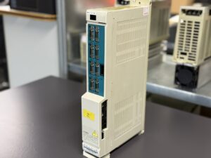
The Mitsubishi Servo Drive Unit MDS-A-V2-1005 was delivered as an axis amplifier from a CNC machine. According to the customer, the fault occurred reliably after a short runtime. After switching on and enabling the axis, the system initially started, but during the first positioning cycle it stopped with alarm Al. 50. It was notable that the alarm did not occur during a hard collision, but already during normal machining, often in the range of low speeds and when holding position. The operator action was always similar: switch on the NC, enable the axis, reference, then a positioning move or holding under load, after which the alarm occurred and the axis was locked.
Incoming inspection and first diagnosis
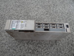
During the visual inspection, the device showed no external mechanical damage. The connections and front surfaces were intact, but a clear contamination in the area of the air paths was visible. For the test bench, the drive was operated with a suitable DC supply and separate control voltage. The fault was reproducible: during repeated positioning movements and moderate load simulation, the motor current rose noticeably quickly. After a short thermal warm up phase, alarm Al. 50 was triggered again. This allowed a pure operator or parameter topic to be narrowed down as the sole cause, because the behavior also occurred with plausible basic parameters as soon as torque was demanded.
Technical analysis
Alarm Al. 50 corresponds to an overload monitoring function in this series. The control evaluates the motor current via a time dependent I²t function. If a defined current portion is exceeded for too long, the drive reports overload and switches off to protect the power section and motor thermally. The analysis showed a cause effect chain of increased losses and reduced heat dissipation: contaminated air paths worsen cooling, the internal temperature rises early and the available continuous current capability decreases. At the same time, age related behavior in the DC link and in the thermal coupling leads to stronger residual ripple and thus to higher current peaks at low speed and during holding. Exactly these current peaks cause the overload integration to rise faster, even if the process is not mechanically blocked. This explains why the alarm occurred preferentially during positioning and holding torque and why it came faster with increasing warm up.
Repair measures and refurbishment
The drive was completely cleaned and the airflow path was made free again. In addition, the cooling function of the device was overhauled, including restoring a stable heat transfer of the load carrying assemblies to the heatsink. The energy path was revised preventively to reduce voltage instability under load and current peaks. Finally, all plug and shielding connections were checked, the internal power supply was checked under load and a parameter plausibility check was carried out. As a preventive measure, maintenance intervals for cabinet filters and air paths were recommended as well as a thermal assessment of the installation situation, because continuous current capability depends directly on ambient temperature and airflow.
Final functional test
The functional test was carried out on the test bench with DC link voltage in the range 270 to 311 V and separate AC control supply 200 to 230 V. Tested were power on and off behavior, enable, reference run and repeated positioning across the entire speed range, including stable runs at low speed and holding under load simulation. In parallel, motor current, DC link voltage and device temperature were monitored. In addition, protection functions such as overcurrent and temperature monitoring as well as signal monitoring of the feedback were checked. After the refurbishment, the drive operated stably, the current profile remained reproducible and alarm Al. 50 did not occur again in continuous operation.
Conclusion
The failure was caused by a combination of reduced cooling performance and age related stress in the energy and power path. This led to increased current peaks and thus to the response of the overload monitoring Al. 50. Through cleaning, thermal overhaul and preventive stabilization of the energy supply, the current carrying capability was restored. The final test bench test confirmed fault free, thermally stable operation. The measures are sustainable because they address the cause and the typical aging risks of these production years.


To mentioned Mitsubishi Drive: Mitsubishi MDS-A-V2-1005 Servo Drive Unit
More details about our Mitsubishi repair services can be found here:
Mitsubishi drive Repair by Industrypart
📞 Feel free to contact us with any questions about your Mitsubishi drive technology.
Our expert team is happy to help!
Technical specifications
| Field | Value |
|---|
| Manufacturer | Mitsubishi Electric Corporation |
| Device type | Servo Drive Unit, AC servo controller for CNC axes |
| Model designation | MDS-A-V2-1005 (according to the nameplate) |
| Series | MDS-Q-V2 |
| Power | approx. 1.0 kW (depending on the connected motor) |
| Input voltage | DC 270 to 311 V, 11 A (power) plus AC 200 to 230 V, 50/60 Hz, 0.2 A (control) |
| Output voltage | 3 AC, PWM, approx. 0 to 230 V |
| Rated current | 3.4 A continuous, 6.8 A short time (according to the nameplate) |
| Control type | digital current and speed controller, positioning via CNC |
| Feedback | approx. encoder feedback, depending on the motor (incremental or absolute) |
| Cooling | approx. air cooling with active airflow |
| Degree of protection | approx. IP20 (control cabinet device) |
| Ambient temperature | approx. 0 to 45 °C (depending on installation situation) |
| Mounting | control cabinet, modular drive unit |
| Origin | Japan |
| Product status | discontinued, legacy system |
Operating environment and possible applications
• Typical machines: CNC machining centers, lathes, gantry machines, handling systems with axis positioning
• Typical years: approx. mid 1990s to early 2000s, nameplate of this device 97/08
• Applications: positioning, interpolated axis movements, holding under torque, dynamic accelerations
• Requirements for environment and control cabinet: clean airflow, filter maintenance, sufficient clearance for air circulation, stable supply, EMC compliant shielding
• Notes on thermal and electrical load: continuous current capability decreases with ambient temperature, high cycle rates increase thermal load, long motor cables and poor shielding increase current peaks
Functional description
• Basic function: conversion of the DC link voltage into a controlled 3 phase supply for the servo motor
• Interaction of power section, control and feedback: current control loop as the basis, above it speed and position control via the feedback, setpoints typically from the CNC
• Enable and protection logic: axis enable only with plausible supply and plausible signals, overcurrent, overload I²t and temperature monitoring protect motor and power path
• Signal monitoring: feedback and communication are monitored for failure and plausibility, in case of a fault a defined shutdown is performed
• Safety relevance: protection functions prevent thermal damage, uncontrolled movement and consequential damage to machine and workpiece
Alarm messages and troubleshooting
| Alarm code | Description | Possible cause | Recommended action |
|---|
| 50 Al. 50 OL1 | Overload 1, I²t shutdown | Persistently high motor current due to load, increased friction, insufficient cooling, parameterization not suitable | Check mechanics and load, check cooling and airflow, check parameters for current limits and acceleration, test run with temperature monitoring |
| 51 OL2 | Overload 2, second overload stage | Like OL1, but stricter threshold or different operating state | As for OL1, additionally evaluate duty cycle and cycle time |
| 3A OC | Overcurrent | Short term current peak too high, cable fault, faulty load, wrong motor assignment | Check motor cable and shielding, insulation measurement, reduce setpoint steps, compare motor data |
| 3B PMO | Overtemperature in the power path | Cooling insufficient, environment too warm, air paths blocked, high continuous load | Clean air paths, check installation situation, adjust load profile, perform thermal test run |
| 46 OHM | Motor overtemperature | Motor temperature signal active, motor overloaded, motor cooling insufficient | Check motor and ventilation, reduce load, check parameters and current limiting |
| 42 FE1 | Feedback error 1 | Signal interruption, interference due to shielding, encoder not plausible | Check plug contacts, check shielding and grounding concept, measure signal quality, check motor encoder |
| 43 FE2 | Feedback error 2 | Deviation between setpoint and actual value, unstable feedback, mechanics stiff | Check mechanics, check control parameters, check feedback, test run at low speed |
| 37 PE | Parameter error | Invalid parameter value, wrong parameter set | Compare parameters, load default values, recommission axis, save and restart |
| 38 TP1 | Protocol error 1 | Communication frame faulty, interference, wrong interface parameters | Check cable and shielding, check plug contacts, compare interface parameters, minimize interference sources |
| 39 TP2 | Protocol error 2 | Communication content implausible, controller sends faulty data | Align controller and drive parameters, check diagnostic logs, check firmware compatibility |
| 34 DP | CRC error | Data transmission faulty, interference, grounding issue | Check shielding, grounding, cable routing, improve EMC measures |
| 88 WD | Watchdog | Software sequence monitoring reacts, internal process fault | Stabilize supply, test restart, rule out thermal causes, if repeated perform electronics overhaul |
Alarm overview based on the available MDS-A/B-V1 alarm table, Al. 50 is listed there as Overload 1,
Assembly overview
| Assembly | Designation (functional, no part numbers) | Function | Notes for testing or repair |
|---|
| Power input and DC link | DC energy supply and energy buffer | Supplies the power path, stabilizes voltage | Check DC link voltage under load, observe ripple, document thermal anomalies |
| Control supply | internal auxiliary supply | Supplies control and monitoring | Check voltages in cold and warm state, check reset behavior |
| Power inverter | 3 phase motor control | Generates controlled motor currents from the DC link | Measure current profile, check protective shutdowns, assess thermal coupling |
| Control and monitoring | current, speed and protection logic | Control loops, I²t overload, diagnostics | Parameter plausibility, alarm history, test reproducibility under load |
| Feedback interface | encoder input and signal processing | Captures actual values for speed and position | Check signal quality, shielding, plug contacts, evaluate FE faults |
| Communication to controller | NC interface | Enable, setpoints, status and diagnostics | Correlate protocol faults TP and CRC faults DP with EMC checks |
| Cooling | airflow and thermal path | Removes heat from the device | Clean air paths, evaluate installation situation and cabinet ventilation |
| Protection functions | overcurrent, overload, temperature | Safe shutdown at limits | Verify thresholds and response behavior on the test bench |