07.11.2025 by Viktor Siebert
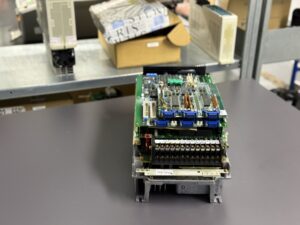
Repair of a Mitsubishi MR-S3-33AA-E01 Servo Drive
Error Description Alarm 32 “Overcurrent”.
According to the Mitsubishi service manual (page I-37), Alarm 32 means:
Overcurrent A current exceeding the allowable value has flowed into the DC bus inside the unit.
Typical causes:
- Defective power module (IGBT transistors)
- Short circuit between phases U/V/W or between the DC bus and ground
- Fault in the driver circuit of the power stage
- Faulty motor or encoder wiring
- Internal failure in feedback or current detection
Recommended troubleshooting steps according to the manual:
- Disconnect power, remove the card, and measure transistor resistance (see table page I-38)
- Check for short circuits between emitter, collector, and driver
- Replace defective modules and power up gradually
Repair Process
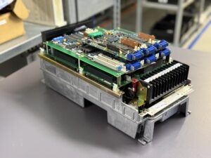
The received MR-S3-33AA-E01 showed Alarm 32 on all three axes immediately after switching on. This indicated a systemic error in the main power circuit, not in a single axis. After disassembly, the following steps were carried out:
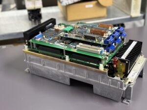
- Visual Inspection:
- Heavy discoloration in the area of the power stages.
- Several electrolytic capacitors showed clear thermal aging.
- No visible defect on the control boards, but minimal soot traces on the backside of the power board.
- Transistor Testing:
- All three axis groups showed identical low resistance between DC bus and output phases (short circuit suspicion).
- This indicated a common failure in the main power supply rail.
- Axis Separation:
- After removing the individual power modules, it became clear that the driver for the L-axis also caused a breakdown.
- The protection circuit reacted too late, which triggered Alarm 32 on all axes.
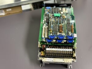
- Repair Measures:
- All IGBT modules and driver boards were removed and tested with replacement modules.
- Control board cleaned, tantalum capacitors and gate resistors renewed.
- Copper traces beneath the heat sink treated with insulating lacquer.
- After repair: full voltage, signal, and temperature testing in idle and load operation.
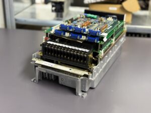
- Test Run:
- Unit tested on a dedicated test bench with three identical HA33/23 motors.
- All axes ran stable, current waveforms symmetrical, IGBT temperature below 45 °C after 60 minutes.
- No new Alarm 32 or secondary error occurred.
Root Cause Analysis
The simultaneous triggering of Alarm 32 on all axes clearly points to overcurrent detection in the shared DC supply.
The cause was insulation degradation in one of the power modules, resulting in asymmetric feedback on the DC link. Due to the common monitoring circuit for all axes, this immediately caused a global shutdown.
Preventive Measures
- Replace all electrolytic capacitors and gate driver components regularly (every 10 years or 30,000 operating hours).
- Replace fan and thermal paste during each service.
- Activate voltage release with a delay of at least 2 seconds to avoid inrush peaks.
- Always verify DC bus voltage before power-up: max. 310 V DC.
Conclusion
After complete overhaul, the MR-S3-33AA-E01 was successfully restored.
All three axes operate stably, the overcurrent protection works correctly, and the current symmetry is within tolerance.
With preventive maintenance, future failures of this generation can be avoided especially through replacement of aged transistor modules and maintaining a controlled thermal environment.
To mentioned Mitsubishi Drive: Mitsubishi Servo Drive MR-S3-33AA-E01
More details about our Mitsubishi repair services can be found here:
Mitsubishi drive Repair by Industrypart
📞 Feel free to contact us with any questions about your Mitsubishi drive technology.
Our expert team is happy to help!
Technical Description
The Mitsubishi MR-S3-33AA-E01 is a three-axis AC servo amplifier of the MR-S3 series, designed for high-precision multi-axis drives in machine tools. Each axis (L, M, and S) can be operated individually with motors such as the HA33/23, where the MR-S3-33AA-E01 version provides approximately 0.3 kW per axis.
The unit operates with an input voltage of 3 × 200–230 V AC, generates a DC bus voltage of approximately 270–310 V DC, and supplies the motors through IGBT power stages. It includes several internal monitoring circuits for overcurrent, overvoltage, temperature, phase loss, and regenerative operation.
Typical Connected Motors
| Axis | Typical Motors | Power | Rated Torque |
|---|
| L-Axis | HA33/23 | 0.3 kW | 2.8 Nm |
| M-Axis | HA33/23 | 0.3 kW | 2.8 Nm |
| S-Axis | HA33/23 | 0.3 kW | 2.8 Nm |
The motors are usually equipped with resolvers or incremental encoders that provide their position feedback to the axis controllers.
Alarm Table (Excerpt Relevant to MR-S3 Series)
| Alarm No. | Description | Cause | Action |
|---|
| 10 | Undervoltage | AC input voltage too low | Check power supply |
| 11 | Axis Error | Encoder position error | Check cables |
| 17 | Board Error | Fault on main board | Replace board |
| 30 | Over-Regeneration | Overloaded resistor | Check resistor |
| 31 | Overspeed | Motor overspeed | Check parameters |
| 32 | Overcurrent | Overcurrent on DC bus | Check power stage |
| 33 | Overvoltage | DC bus above 400 V | Check supply voltage |
| 45 | Fin Overheat | Heatsink over 85 °C | Check cooling |
| 46 | Motor Overheat | Motor protection active | Check motor |