14.03.2026 by Viktor Siebert
Mitsubishi MR-S12-80B-Z33 servo drive with alarm A.17 on enable, cause in the power board after improper pre repair
Initial situation and fault pattern.
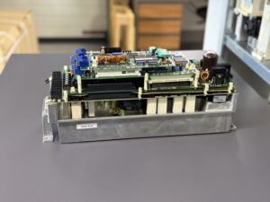
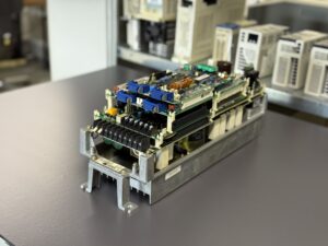
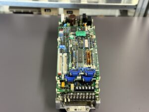
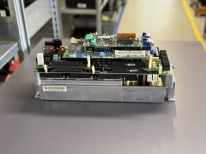
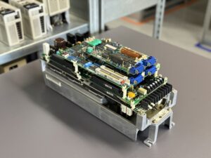
A Mitsubishi MR-S12-80B-Z33 servo drive from a 2 axis application with L axis and M axis was delivered. The fault occurred reproducibly directly on enable. As soon as Servo ON was commanded, alarm A.17 appeared immediately. No start up or axis movement took place.
The condition on arrival was notable. The unit arrived pre repaired. In the power area, assemblies had been replaced and re soldered. The solder joints were uneven and partly mechanically unstable. In addition, an electrolytic capacitor was swollen, which had been operated with reversed polarity due to incorrect installation. Also, optical isolation functions of an incorrect type had been installed. This overall picture indicated consequential damage caused by improper intervention, not a normal aging fault.
Incoming inspection and first diagnosis
Before any work, the rule applied: switch off power, secure against re energizing, wait for discharge time, verify absence of voltage. Then a visual inspection was performed focusing on thermal traces, contact points and mechanical stress. The indications of improper previous work were confirmed.
The fault was reproduced on a test setup. Alarm A.17 occurred immediately on enable. For isolation, the power unit and both control boards were swapped against verified reference assemblies. With a verified power assembly, the power unit and both control boards of the customer drive operated without faults. This localized the cause clearly to the power board of the delivered unit.
The battery was measured and was at 3.6 V, therefore within range. A battery related loss of absolute data was unlikely as the primary cause, even though the Z33 variant uses absolute position detection.
Technical analysis
An alarm directly on enable typically occurs when the internal self test of the power stage fails. On Servo ON, the MR S12 checks several safety and plausibility criteria, including internal supplies, drive logic, current feedback and signal paths of the power stage. If measured values are implausible, the protection logic blocks immediately before motor current is built up.
For A.17, the technical direction is clear: A/D converter error or current feedback error. This matches the findings. Incorrect optical isolation can distort timing and logic of power drive signals. Poor solder quality leads to transition resistance and intermittent opens. An energy storage function damaged by reversed polarity loads internal supply rails and increases disturbance levels. Together this produces values outside allowed windows and enable is blocked immediately.
In addition, for this series it is important that this is an integrated 2 axis amplifier. The L axis is designed for the larger motor capacity. Incorrect assignment of motors to the axis can lead to severe consequential damage. The manual explicitly warns not to operate a smaller capacity motor on the L axis, because the motor can become demagnetized. For diagnosis this means that besides the drive, axis assignment, feedback and parameterization must also be plausible.
Repair actions and refurbishment
Repair was performed without naming individual parts, focusing on function critical assemblies. First, all improper rework was reverted. The affected energy area was professionally reworked, correctly polarized and electrically stabilized. Optical signal coupling was brought back to a specification compliant type. Critical contact points and solder connections were mechanically stabilized and verified to prevent intermittent faults later.
In addition, connectors and contact surfaces were cleaned and checked for a tight fit. The cooling path was checked because thermal stress influences drift of sensing paths and lifetime of the power stage. Preventively, control cabinet suitability was assessed, especially airflow, filter condition and fan operation.
Final functional test
The functional test was performed on a test bench with 3 phase supply and suitable measurement equipment. Tested were power on and off behavior, repeated enable cycles, warm up, and controlled operation at low, medium and higher speed ranges with load simulation. Special attention was given to low speeds because current sensing and control are particularly sensitive to disturbances there.
After repair, alarm A.17 no longer occurred. Enable was stable and reproducible, also after multiple cycles and after thermal warm up. Measurements on live parts were carried out exclusively by a qualified electrician with suitable equipment and according to local rules.
Conclusion
The A.17 enable fault was clearly caused in the power board. The power unit and both control boards were normal with a verified power assembly, and the battery at 3.6 V was within range. The cause was improper pre repair with incorrect signal coupling, poor solder quality and consequential damage in the energy area.
Through professional stabilization of the affected functional areas, correction of the signal coupling and test bench verification across enable cycles and speed ranges, sustainable function was restored. In addition, the system logic of the 2 axis design was considered to avoid consequential damage caused by incorrect axis assignment.
More details about our Mitsubishi repair services can be found here:
Mitsubishi drive Repair by Industrypart
📞 Feel free to contact us with any questions about your Mitsubishi drive technology.
Our expert team is happy to help!
Technical specifications
| Field | Value |
|---|
| Manufacturer | Mitsubishi Electric |
| Device type | 2 axis servo drive, integrated servo amplifier |
| Model designation | MR-S12-80B-Z33 |
| Series | MR-S12 |
| Power | L axis approx. 1.0 kW, M axis approx. 0.5 kW |
| Input voltage | 200 or 220 V AC, 3 phase, 50 or 60 Hz |
| Output voltage | 155 Vrms |
| Rated current | input current approx. 9.1 A at 100 percent load |
| Control method | sine wave PWM system |
| Feedback | Z33 absolute position detection, requires suitable detectors and battery buffering |
| Cooling | internal cooling, control cabinet air, depending on installation and airflow approx. |
| Protection class | approx. IP20, control cabinet mounting |
| Ambient temperature | 0 to 55 °C operation |
| Mounting | vertical on mounting plate in the control cabinet |
| Origin | unknown |
| Product status | discontinued or service stock, depending on machine approx. |
| Power consumption | 2.6 kVA at 100 percent load |
Operating environment and typical applications
Typical environments are machine tools, handling systems and multi axis feed systems. Typical machine years are approx. 1995 to 2005. The MR S12 is operated in the control cabinet and requires stable supply, clean grounding and EMC compliant shielding of motor and feedback cables.
Thermally critical are clogged filters, weak fans and excessive cabinet temperature. Electrically critical are loose incoming terminals, contactor issues, voltage dips and disturbances affecting feedback and signal lines. In 2 axis systems, correct assignment of motors to the axis is mandatory. The manual warns not to operate a smaller capacity motor on the L axis, because demagnetization may occur.
Functional description
The MR S12 is an integrated 2 axis servo amplifier for the L axis and M axis. It converts mains voltage into a controlled motor supply and regulates torque and speed via current controlled PWM. The feedback provides actual values for control and protection logic. In the Z33 variant, absolute position detection is supported, which requires suitable detectors and battery buffering.
On enable, the unit checks internal supply rails, plausibility of current feedback, signal paths of the power drive and protective functions. Protection logic monitors overcurrent, over and undervoltage, temperature and feedback. These functions are safety relevant because incorrect drive can cause high currents or uncontrolled motion within a very short time.
Alarm messages and troubleshooting
| Alarm code | Description | Possible cause | Recommended action |
|---|
| A.17 | A/D converter error, current feedback implausible | current feedback sensing path disturbed, incorrect signal isolation, unstable internal supply, pre repair error | check power board, verify internal supplies and sensing paths, restore specification compliant signal coupling, test bench enable cycles |
| 10 | Insufficient voltage DC bus | mains voltage dip, unstable incoming power, contact issue | check supply under load by a qualified electrician, check terminals and contactors |
| 11 | Axis selection error | axis selection or assignment incorrect | verify axis assignment, correct switch setting, plausibilize parameters |
| 12 | Memory error during power on self test | internal hardware fault, consequential damage | save event history, inspect assembly, typically repair or replacement |
| 13 | Software processing error | noise or unstable supply | check grounding and shielding, stabilize supply, reproduce on test bench |
| 16 | Pole position detection error | feedback or start sequence implausible | check commissioning sequence, verify feedback, check parameters and axis assignment |
| 18 | Initial feedback communication error | connector, cable, detector or interface issue | check external connectors, measurements only by a qualified electrician, test feedback on a bench |
| 24 | Ground fault | motor cable or motor insulation issue | insulation test only by a qualified electrician, check cable set, assess moisture and contamination |
| 25 | Absolute position data lost | battery or absolute function interrupted | check battery voltage, re establish absolute data, check feedback and supply |
| 30 | Over regeneration | braking energy too high, braking circuit overloaded | check decel ramps, check braking circuit and cooling, assess mechanical load |
| 31 | Overspeed | feedback implausible or limits exceeded | check limits, verify feedback plausibility, check mechanics and load |
Assembly overview
| Assembly | Functional designation | Function | Notes for testing or repair |
|---|
| RG201 control board | Control card | control, enable logic, signal processing | reference swap, check connectors, bench verification |
| RG221 base board | Base card | interfaces and signal distribution | visual inspection, check connectors, plausibilize signal paths |
| RG21B-80B power board | Power card | power drive, current sensing and protection paths | main focus for A.17, verify signal coupling and sensing paths, professional rework |
| 80B power unit | Power unit | energy conversion and DC link functions | thermal inspection, check contact surfaces, load simulation and warm up test |