28.11.2025 by Viktor Siebert
Repair of a Mitsubishi MR-J2S-40A AC Servo Drive Unit with AL.24 Main circuit error
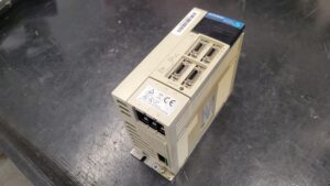
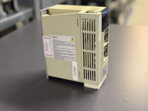
The MR-J2S-40A arrived in our workshop with the fault that the servo amplifier triggered alarm AL.24 immediately after the main circuit was energized. AL.24 is one of the decisive protective alarms in the MR-J2S series and clearly indicates a ground fault or an interruption in the main power path of phases U, V and W.
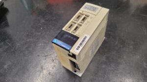
During the first visual inspection it became evident that the unit had been operating for an extended period in a machine environment with high dust and oil mist exposure. The cooling channels were partially clogged and the heat sink showed darkened areas that suggested elevated thermal load over time.
As with every incoming device, the repair process began with a full electrical isolation and a structured intake measurement. The insulation test of the motor cables, which the customer had already performed, showed no abnormal values. This shifted the initial suspicion away from the external wiring and toward an internal failure of the power section.
Our first controlled test on the in house drive test bench confirmed this assumption. Even with the motor completely disconnected, the servo amplifier shut down the main power stage and displayed AL.24 immediately. According to the MR-J2S manual, this behavior occurs when the error persists after disconnecting U, V and W, indicating that the ground fault is created inside the drive itself.
After opening the servo amplifier, the technical cause could be identified. The power board J2S-P03 showed clear thermal discolorations around the driver section. The insulation barriers between gate driver and IPM module contained several microscopic carbonized areas. These are typical signs of leakage currents caused by heat, dust and conductive residues. Several solder joints around the high current section showed dull surfaces which confirmed long term thermal stress and beginning micro cracking.
The next step was the complete removal of the power module. The defective IPM was desoldered from the board and replaced with a verified original part. The electrolytic capacitors of the DC bus were checked and showed values below their nominal tolerance limits. They were replaced as a preventive measure.
The gate driver circuit was fully measured. Although most components were within specification, two critical optocouplers were replaced to ensure long term stability of the switching behavior.
After restoring the power section, the entire PCB was cleaned in a multi stage process. Residual dirt, flux and dust were removed because such contamination increases the likelihood of leakage currents, which is directly relevant for AL.24.
Following the electronic repairs, the functional testing phase began. The servo amplifier was connected to our test stand, where it was supplied with 230 V AC and driven in predefined load cycles. Special attention was given to the initialization phase, since AL.24 often appears at the moment the DC bus charges. After repeated power cycles, the DC bus remained stable and no abnormal current paths were detected.
Subsequently, a dynamic motion test was performed with defined speed and torque sequences. Parameters such as current ripple, switching noise, thermal rise and encoder feedback signals were monitored continuously. All values stayed within the allowed limits.
The final step consisted of a prolonged endurance test. The drive ran for several hours under alternating load conditions that simulate typical machine operations. No irregularities occurred. The servo amplifier remained thermally stable, the current patterns were clean and no protective function was triggered. Only after this complete procedure the device was released.
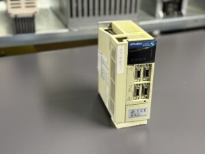
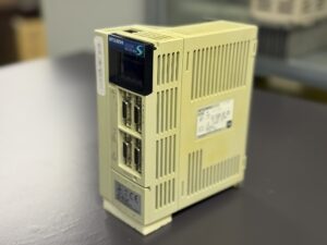
The customer received a fully refurbished MR-J2S-40A in which the power board had been renewed, the internal components had been cleaned and the thermal stability had been restored.
This case demonstrates how sensitive the MR-J2S generation can be to environmental contamination and how important preventive maintenance is for long term operational reliability.
Preventive Measures for the Customer
- Regular cleaning of the cooling paths and cabinet interior
- Annual insulation testing of motors and cables
- Replacement of the internal fan every three to five years
- Detailed inspection of plugs, shields and grounding
- Avoiding oil mist inside the cabinet
- Preventive replacement of aged capacitors and stressed connectors
Conclusion
Alarm AL.24 is a critical protective function in the MR-J2S-40A. A structured diagnostic process and a technically sound repair restore full functionality and significantly extend the lifetime of the drive.
More Info & Contact
To mentioned Mitsubishi Drive: Mitsubishi MR-J2S-40A Servo Drive Unit
More details about our Mitsubishi repair services can be found here:
Mitsubishi drive Repair by Industrypart
We regularly repair similar models, including:
MR-J2S-40B
MR-J2S-40B4
MR-J2S-40A-QW219
Technical Specifications
| Parameter | Value |
|---|
| Manufacturer | Mitsubishi Electric |
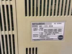
| Model | MR-J2S-40A |
| Type | AC servo drive, 400 W |
| Input | 3PH+1PH 200 to 230 V, 50/60 Hz, 2.6 A |
| Output | 170 V, 0 to 360 Hz, 2.8 A |
| Control interface | CN1A and CN1B, optically isolated |
| Encoder feedback | CN2, 131072 pulses per revolution |
| Cooling | Convection, internal fan |
| Weight | approx. 1.5 kg |
| Serial number | N28J68014 |
| Manual reference | MR-J2S troubleshooting section |
Application Environment and Compatible Devices
The MR-J2S-40A is used in CNC machine tools, handling systems and compact industrial automation modules. Typical applications include high dynamic positioning axes, feed axes in milling and turning machines and automated assembly systems.
Compatible motors: HF-K, HF-M and HF-S series, also certain HA motors with the appropriate encoder type.
Environmental requirements: 0 to 55 degrees Celsius, dry control cabinets with sufficient ventilation, EMC compliant wiring and shielded encoder lines.
Functional Description
The MR-J2S-40A converts the incoming supply voltage into a controlled DC bus which feeds the internal three phase power module. This module generates the U, V and W motor phases and regulates current, speed and position via a multilayer control algorithm.
The control logic processes pulse commands, analog commands or serial commands, monitors feedback from the encoder and supervises voltage, current, temperature and internal safety paths.
If irregular feedback or a hazardous electrical condition occurs, the drive initiates a dynamic stop and displays the corresponding alarm. Alarm AL.24 is a critical fault indicating a ground fault or an internal main circuit defect.
Alarm Messages and Troubleshooting
| Code | Description | Cause | Solution |
|---|
| AL.10 | Undervoltage | Supply voltage too low or unstable | Check the power source |
| AL.12 | Memory error 1 | RAM failure | Replace the drive |
| AL.13 | Clock error | Fault on printed circuit board | Replace the drive |
| AL.15 | Memory error 2 | EEPROM error | Replace the drive |
| AL.16 | Encoder error 1 | CN2 disconnected or encoder defective | Check motor and cable |
| AL.24 | Main circuit error / ground fault | Ground fault on U, V or W, internal power stage failure | Check motor and cable, replace drive if required |
| AL.30 | Regenerative alarm | Regeneration overload or resistor fault | Check load and resistor |
| AL.31 | Overspeed | Faulty feedback or incorrect command | Check encoder and parameters |
| AL.32 | Overcurrent | Short circuit in motor or power module | Inspect motor, replace drive |
| AL.33 | Overvoltage | DC bus voltage abnormal | Check power supply |
| AL.50 | Overload 1 | Continuous overload | Check mechanics |
| AL.51 | Overload 2 | Collision or excessive torque | Check the machine |
Components
| Assembly | Designation | Function |
|---|
| Power board | J2S-P03 or BS368A615G53 | Power module and main circuit |
| Control board | Integrated logic board | Signal processing and control |
| Power supply stage | AC to DC converter | DC bus supply |
| Gate drive section | Optocoupler driven control | IPM control sequence |
| Cooling system | Heat sink and fan | Heat dissipation |
| CN connectors | CN1A, CN1B, CN2 | I/O and encoder |