03.11.2025 by Viktor Siebert
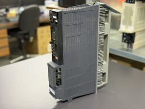
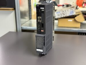
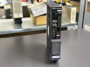
Repair of a Mitsubishi MDS-DH2-V2-2020 Servo drive Unit
Description and Initial Situation
A Mitsubishi MDS-DH2-V2-2020 Servo Drive Unit arrived at our workshop after the device suddenly failed to power up on a Monday morning at the customer’s facility. The machine stopped completely, and the drive’s status LEDs remained dark. Despite several restart attempts, the unit did not respond. The customer replaced it with a spare drive from another machine to resume production immediately, which confirmed that the fault was located within the drive itself.
Technical Specifications
| Specification | Value |
|---|
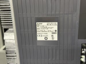
| Manufacturer | Mitsubishi Electric |
| Series | MDS-DH2 |
| Device Type | Servo Drive Unit |
| Model Number | MDS-DH2-V2-2020 |
| Input Voltage | 3 × 380–440 V AC, 50/60 Hz |
| Output | 3 × 9.3 A, 0–240 Hz |
| Power | 1.0 / 1.3 kW |
| Production Date | 2023-04 |
| Control Board | RM120C-22 F / BC886A159G51 |
| Power Board | RM162C-V2 / BC886A010G53 P |
| Power Module | BKO-NC1207 H84 A2-DH2-V2-2020 |
his configuration of control, power, and final stage modules is widely used in Mitsubishi and Okuma CNC systems. The modular structure ensures precise control under high torque requirements and reliable communication with the main controller.
Fault Analysis
Initial inspection revealed that the DC bus voltage was missing, although the AC supply was present and stable. The input phases (L1, L2, L3) were fine, as were the fuses. During the charging phase, however, no current flowed through the inrush circuit, indicating a defect either in the primary circuit or the rush circuit relay.
No LED indicators were lit, confirming a problem within the power or control supply section. After disassembly, a thermal discoloration was visible on the power board. Further analysis showed that the inrush current control circuit had failed—matching the description of Alarm 6B (Rush Circuit Error) from the MDS-D/DH manual.
Diagnostic Process
After separating the modules, the capacitor banks were manually charged and tested; capacitance values were normal. The inrush resistor and relay were then checked in detail. The relay was mechanically stuck, although the coil itself was intact. This caused the unit to remain unpowered during startup.
Due to the voltage failure, the control board had also logged multiple failed start sequences. After full cleaning, reflow repair of the secondary power section, and interface testing, the module was restored.
Relevant error references from the MDS-D/DH Series Instruction Manual include:
| Alarm No. | Description | Reset Method |
|---|
| 6B | Rush Circuit Error | PR |
| 6C | Main Circuit Error | PR |
| 68 | Watchdog | AR |
| 71 | Instantaneous Power Interruption | NR |
| 72 | Fan Stop | PR |
| 77 | Power Module Overheat | PR |
Source: MDS-D/DH Series Instruction Manual, Section 6-2-1 ff.
Repair Procedure
The defective power board RM162C-V2 was removed and inspected. After replacing the damaged relay, cleaning the inrush circuit, and performing a preventive capacitor replacement, the module was reassembled. The cooling fan circuit (Alarm 72/EE) was also checked, and all fans were replaced due to expected wear after approximately 10,000 operating hours.
The control board RM120C-22 F was visually and electrically inspected. Minor irregularities in the DC/DC converter area were corrected, and the firmware was reinitialized.
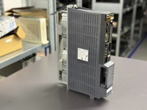
Once the unit was reassembled, it was tested on our Mitsubishi test bench using an HC series servo motor and load simulation. All axes responded normally, parameters remained within tolerance, and no faults reappeared.
Preventive Measures
Since the failure was caused by a worn inrush relay, we recommend preventive inspection or replacement of the inrush relay assembly on similar units. Cooling fans should be replaced every 3–4 years, depending on the environment, to prevent thermal overload. In machines operating under oily or dusty conditions, routine cleaning and insulation testing should be carried out regularly to prevent premature failures.
Quality Assurance and Final Testing
After reassembly, the drive underwent extended testing under variable load conditions. Several hours of operation were performed, including acceleration, deceleration, and torque change tests. The temperature of the power transistors remained stable, DC bus voltage was constant, and no new alarms occurred.
Following this endurance testing, the unit passed all quality checks and was released for shipment back to the customer.
Conclusion
The failure of the MDS-DH2-V2-2020 drive was caused by a mechanical malfunction in the inrush relay. Through complete refurbishment, preventive component replacement, and recalibration, the drive was fully restored to operational condition.
Such faults are typical for high-hour units and emphasize the importance of preventive maintenance, periodic inspections, and keeping the drive’s internal cooling and power circuits in optimal condition for long-term reliability.
To mentioned Mitsubishi Drive: Mitsubishi MDS-DH2-V2-2020 Servo drive Unit
More details about our Mitsubishi repair services can be found here:
Mitsubishi drive Repair by Industrypart
📞 Feel free to contact us with any questions about your Mitsubishi drive technology.
Our expert team is happy to help!