04.03.2026 by Viktor Siebert
Mitsubishi MDS-DH-SP-200 spindle drive: alarm 3D after runtime due to impaired cooling
Initial situation and fault pattern.
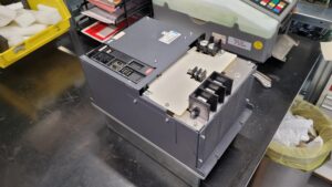
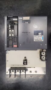
A Mitsubishi spindle drive unit type MDS-DH-SP-200 arrived in the workshop with an intermittent fault. In the machine, the front display showed code 3D, but only after a certain machining time. The display alternated between axis number and alarm number and flickered when an alarm occurred. Typical was warm operation, often associated with accelerating or decelerating the spindle. After a reset and a short cooling phase, the system often started again.
What stood out is that alarms during the process bring the spindle to a stop and are shown at the same time on the CNC monitor and via the LEDs on the drive. This points more to a dynamic protective event than to a purely power up fault.
Incoming inspection and first diagnosis
Before opening or unplugging connectors: switch off power, secure against being switched on again, wait the discharge time, verify absence of voltage. Measurements on live parts only by a qualified electrician.
Visual inspection showed heavy contamination in the air path. Dust, fine chips and an oily film had clogged the cooling paths. The cooling fan started, but at times slowed down and stopped. This made a thermal relationship very likely.
At the test bench, the drive was operated with repeated acceleration and deceleration cycles. When cold, operation remained stable. After warming up and under dynamic load, the fault could be triggered repeatedly, especially when the cooling fan dropped out.
Technical analysis
Alarm 3D is described in the list as Power supply voltage error at acceleration/deceleration. A motor control error is detected during acceleration or deceleration, triggered by a drop in the input voltage.
In the MDS-DH-SP-200, power is provided from a DC link. If the available DC link voltage drops under dynamic load, the protective logic responds. In this case, inadequate cooling amplified the effect: contamination and a cooling fan that stopped intermittently led to rising temperature in the power section, higher losses and lower reserves during load changes. As typical check points for thermal problems, Mitsubishi mentions fan operation, contaminated cooling surfaces and an excessively high control cabinet ambient temperature.
Repair measures and refurbishment
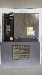
The refurbishment focused on cooling and thermal stability. The device was professionally cleaned inside and out, including air ducts and cooling surfaces. The cooling fan was replaced due to the intermittent stoppage. Connectors in the area of cooling and power routing were checked, cleaned and secured.
In addition, basic tests were carried out: visual inspection of the connection areas, insulation test of the power terminals against the housing, and plausibility checks of feedback and signal connectors. As a preventive measure, regular control cabinet maintenance with filter replacement and temperature monitoring was recommended.
Final functional test
The functional test was performed on the test bench with suitable supply. Runs were carried out at low, medium and higher speeds, each with repeated acceleration and deceleration cycles. A thermal endurance run of approx. 2 hours with load simulation was used to specifically verify the time dependent fault pattern.
Current draw, temperature trend, airflow and protective logic were monitored. After the refurbishment, cooling remained stable, the temperature rise was within the expected range, and alarm 3D could no longer be reproduced.
Conclusion
3D after machining time was a load and temperature dependent protective event. The main cause was impaired cooling due to contamination and a cooling fan that was dropping out. Cleaning, replacement of the fan function and a thermal final test restored operational reliability and reduced the risk of renewed failures.
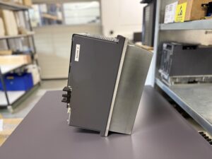
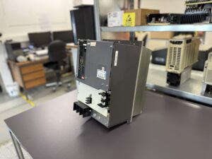
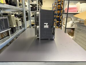
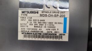
To mentioned Mitsubishi Drive: Mitsubishi MDS-DH-SP-200 Spindle Drive Unit
More details about our Mitsubishi repair services can be found here:
Mitsubishi drive Repair by Industrypart
📞 Feel free to contact us with any questions about your Mitsubishi drive technology.
Our expert team is happy to help!
Technical specifications
| Field | Value |
|---|
| Manufacturer | Mitsubishi Electric |
| Device type | Spindle Drive Unit (spindle drive) |
| Model designation | MDS-DH-SP-200 |
| Series | MDS-D/DH Series |
| Power | 37 kW |
| Input voltage | DC 513 to 648 V (DC link), additionally 1~ 380 to 440 V or 480 V, 50/60 Hz (control, 0.1 A) |
| Output voltage | 3~ 340 V, 0 to 1167 Hz |
| Rated current | Input 99 A DC, output 85 A AC |
| Control type | Digital spindle drive, PWM inverter, vector based speed control (approx.) |
| Feedback | Spindle encoder for speed control, incremental or serial depending on the machine (approx.) |
| Cooling | Forced air cooling via internal fan |
| Protection class | IP00 (approx., installed in control cabinet) |
| Ambient temperature | 0 to 55°C (approx.), clean air flow required |
| Mounting | Vertical in the control cabinet, on mounting plate (approx.) |
| Origin | Japan |
| Product status | unknown, series often in spare parts operation (approx.) |
Operating environment and possible applications
Typical are CNC machining centers, lathes and grinding machines where high dynamics and constant speed stability are required. The MDS-D/DH platform is often found in machines from approx. 2008 to 2015, depending on the CNC system and retrofit status (approx.).
For stable operation, important are:
• sufficient control cabinet cooling and clean air flow
• regular filter replacement so that internal forced ventilation can work
• stable supply without strong voltage dips during load changes
• clean shielding and separated routing of power and signal paths to reduce interference (approx.)
Functional description
The spindle drive converts the energy from the DC link into a three phase, frequency variable output voltage for the spindle motor. A control unit processes setpoints from the CNC, monitors current and voltage, and uses feedback signals from the spindle encoder to stabilize speed and dynamics.
Power stage, control and feedback are coupled via protective logic. In case of deviations such as undervoltage, overcurrent, overload or thermal limit conditions, spindle operation is ended in a controlled manner. The documentation describes that the spindle drive coasts or decelerates to a stop when an alarm occurs and outputs the alarm number via the CNC monitor and LED display. This monitoring is safety relevant because it is intended to prevent consequential damage to the motor, mechanics and power supply.
Alarm messages and troubleshooting
| Alarm code | Description | Possible cause | Recommended action |
|---|
| 3D | Supply voltage error during acceleration/deceleration | voltage dip under load, insufficient supply reserve, thermally induced voltage drop (approx.) | check supply under load, assess ramps and load, check cooling and environment |
| 45 | Fan stop | cooling fan stopped, overheating in the power section | check fan operation, remove contamination, renew fan function, improve environment |
| 3B | Power section overtemperature | air paths clogged, cooling surfaces contaminated, control cabinet too warm | clean fan and cooling surfaces, improve air flow, check control cabinet cooling |
| 10 | Undervoltage DC link | supply unstable, contactor or wiring faulty | check supply and contactors, measure voltage trend, check supply capacity |
| 4F | Short interruption of control supply | 1~ supply briefly missing, terminals loose, mains disturbance | check control supply and terminals, assess mains quality |
| 50 | Overload | continuous load too high, machining too aggressive, incorrect parameters (approx.) | reduce load, adjust ramps, check parameters, verify thermally |
| 3C | Regeneration circuit error | braking energy cannot be processed correctly | check braking concept, check connection and condition of the regeneration path |
| 33 | Overvoltage DC link | regenerated voltage too high during deceleration (approx.) | extend braking ramps, check regeneration path, check mains conditions |
| 87 | Communication error between drives | optical connection or plug loose, interference | check and secure connection, check shielding and routing |
| 46 | Motor overtemperature / thermal error | motor thermally overloaded, sensor problem (approx.) | check load and cooling at the motor, check sensor and connection |
Note: Alarm definitions and stop behavior are based on the MDS-D/DH troubleshooting list.
Module overview
| Module | Functional designation | Function | Notes for testing or repair |
|---|
| Control board | RM111C-11 or BN638A503G51 XK | Control, communication, monitoring | check contamination and corrosion, secure connectors, evaluate fault memory |
| Power board | RM167A-DH-SP-200 or BN638A447G52 C | Driving and measurement of the power stage | assess thermal stress, check air flow, perform basic tests after cleaning |
| Power section | Power section | Power conversion DC to variable 3~ output | test bench run, observe temperature trend and protective functions |