27.10.2026 by Viktor Siebert
Sudden shutdown and control board repair
Sudden shutdown of the Mitsubishi MDS-DH-CV-550
This Mitsubishi MDS-DH-CV-550 Power Supply Unit arrived at industrypart after intermittent shutdowns. The customer reported a small “d” on the LED display, followed by a sudden shutdown. Switching the unit on again was only possible several hours later. Our examination identified damage in the system control and substantial ageing in the power section. According to our workshop diagnosis, insufficient cooling caused the damage.
Unit identification and ratings
| Item | Documented value |
|---|
| Manufacturer / model | Mitsubishi Electric / MDS-DH-CV-550 |
| Unit type | Power Supply Unit, shared supply for servo and spindle drives |
| Nameplate power | 45 kW |
| Mains connection | Three phase, 400 V class, 50/60 Hz; nameplate input current 106 A |
| Control supply | Separate single phase connection; nameplate current 0.1 A |
| Nameplate DC output | 513 to 648 V DC, 119 A |
| Revision shown | Hardware G; software BND588W000A3 |
| Date marking | 07/09 |
| Cooling | Fans and heat sink |
| Motor connection / encoder | Handled by downstream drive units, not directly by this supply |
These nameplate values belong to the pictured unit. Replacement requires matching the power class, mains frequency, control supply and hardware/software revision. This supply is not a standalone motor amplifier. A similar designation or a mechanically compatible connector does not establish interchangeability.
Function in the drive system
The power supply provides the shared DC bus for connected servo and spindle units. Those downstream units perform the actual motor control. During regenerative operation, energy returns from the drive system to the supply. Mains input, charging sequence, power electronics and internal control must work together. A fault in this central supply can consequently affect several drives.
Communication with the drive units carries operating states and fault information. It does not replace examination of the power path. A stopped drive therefore does not automatically imply a faulty motor or encoder. In this case, the confirmed damage was in the power supply system control.
Assemblies and workshop findings
| Assembly | Function | Finding in this case |
|---|
| Control board | Internal sequencing, processing and monitoring | Extensive overhaul required |
| Power stage | Energy conversion and DC bus supply | Several components substantially aged |
| Fans / heat sink | Heat removal | Heavy contamination; fans barely turned and were excessively loud |
| LED display | Operating state and alarm indication | Small d reported by customer |
| Mains and DC bus terminals | Power input and distribution | General system function; no additional individual fault documented |
No circuit board part number was documented for this repair, so none is added here. The fan photograph documents contamination; an enclosure photograph alone cannot establish internal electrical faults.
Why cooling mattered
Deposits restrict airflow. If the fans can barely turn, the actual air delivery decreases further. Losses then produce heat that cannot leave the enclosure effectively. Repeated thermal stress accelerates component ageing and can impair both control and power electronics.
The ability to restart only after several hours is consistent with a temperature dependent fault. That behaviour alone does not prove a particular thermal switch or identify an individual failed component. The decisive evidence came from examining the damaged system control and the deteriorated power section.
A small d does not automatically indicate an alarm
Mitsubishi manual IB-1500025-H, section 6-1-3, explicitly states that solid displays “b”, “C” and “d” do not indicate alarms. The distinction between solid and flashing indication matters. The customer reported a small d but did not confirm whether it flashed. We therefore do not infer a specific alarm or operating state from that report. The sudden shutdown required investigation independently of the displayed character.
Power supply alarm reference
The following manufacturer reference provides technical context. None of these codes was documented as an actual alarm in this repair. Check the unit variant, software revision and complete message before applying a definition. The diagnostic notes are general considerations for qualified personnel, not a record of measurements performed.
| Code | Manufacturer designation | Meaning | Diagnostic context |
|---|
| 61 | Power module overcurrent | Overcurrent in the power module | Distinguish the module, DC bus and connected units. |
| 62 | Frequency error | Input frequency too high | Check supply conditions and frequency. |
| 66 | Process error | Processing cycle error | Examine internal control and interference. |
| 67 | Phase interruption | Supply phase interruption | Check phases, fuses and switching devices. |
| 68 | Watch dog | Incorrect system operation | Check control electronics and their supply. |
| 6A | External contactor welding | External contactor does not open as expected | Distinguish contactor operation and feedback. |
| 6B | Rush circuit error | Inrush current limiting circuit error | Examine charging circuit and switching sequence. |
| 6C | Main circuit error | Main circuit capacitors do not charge correctly | Distinguish supply, charging circuit and connected loads. |
| 6E | Memory error | Memory, A/D or unit identification error | Consider subcode and unit revision. |
| 6F | Power supply error | Power supply not detected or communication error | Isolate connections and the affected unit. |
| 71 | Instantaneous power interruption | Momentary power interruption | Distinguish a supply event from internal shutdown. |
| 72 | Power supply: Fan stop | Fan stop with overheating in the power module | Check fans, air passages and temperature monitoring. |
| 75 | Overvoltage | DC bus overvoltage | Consider supply and regeneration conditions. |
| 77 | Power module overheat | Power module overheating | Examine cooling, environment and loading. |
Isolating the fault rather than interpreting one display
For comparable shutdowns, distinguish an external supply interruption, contactor operation, internal control supply, thermal stress and faults in connected units. The full machine message history and the relationship between temperature, loading and shutdown help isolate the cause. One momentary display is insufficient. Here, damage to the control, ageing components and inadequate cooling justified extensive repair.
Overhaul and test bench documentation
The control board underwent an extensive overhaul. The condition of the power stage was addressed as part of the comprehensive repair. The supplied photographs document the unit after repair, and the video shows the power supply at the test bench.
Preventive maintenance
Changes in fan noise, stiff fans and obstructed cooling paths deserve early attention. Maintenance intervals should reflect actual dust and oil mist exposure and cabinet condition. Keep air passages and filters clear and avoid environmental conditions that impair heat removal. Investigate unusual noise or recurring shutdowns before further thermally stressed assemblies fail.
Manufacturer documentation
Mitsubishi MDS-D/DH Series Instruction Manual, IB-1500025-H, section 6-1-3, printed page 6-8 (PDF page 429): power supply alarms and solid d indication. Unit ratings were also taken from the photographed nameplate.
Test bench video
Before and after repair photographs
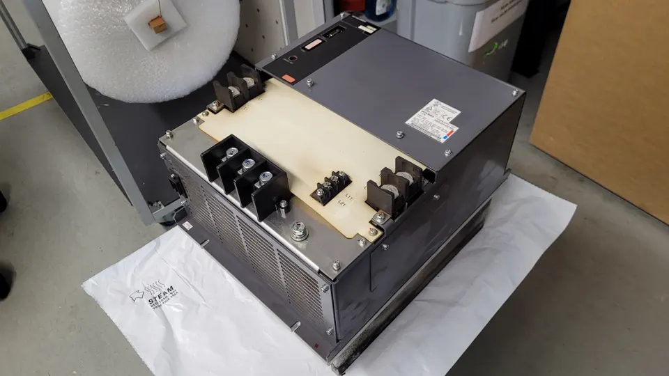 Before repair | Mitsubishi MDS-DH-CV-550
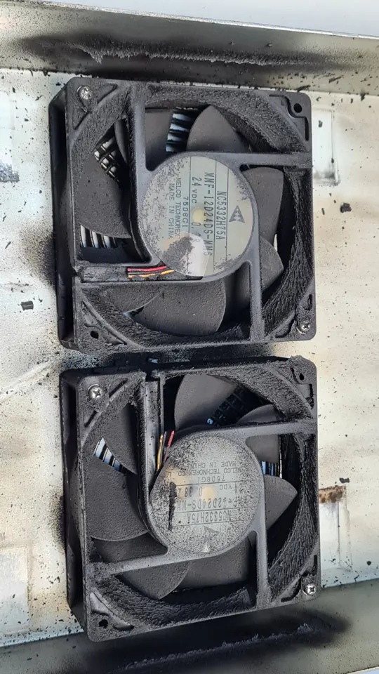 Heavily contaminated fans | Mitsubishi MDS-DH-CV-550
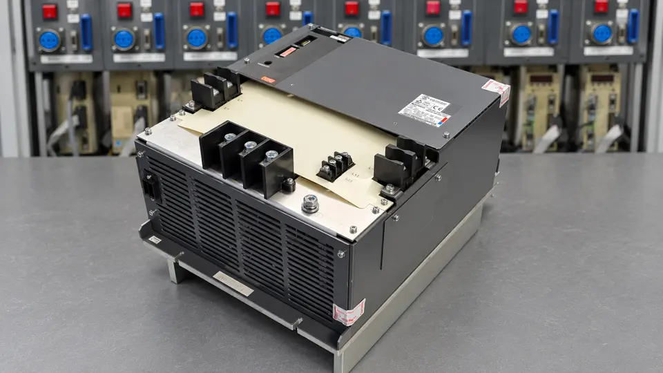 After repair with connections facing forward | Mitsubishi MDS-DH-CV-550
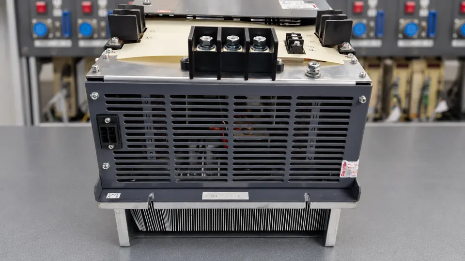 Front view after repair | Mitsubishi MDS-DH-CV-550
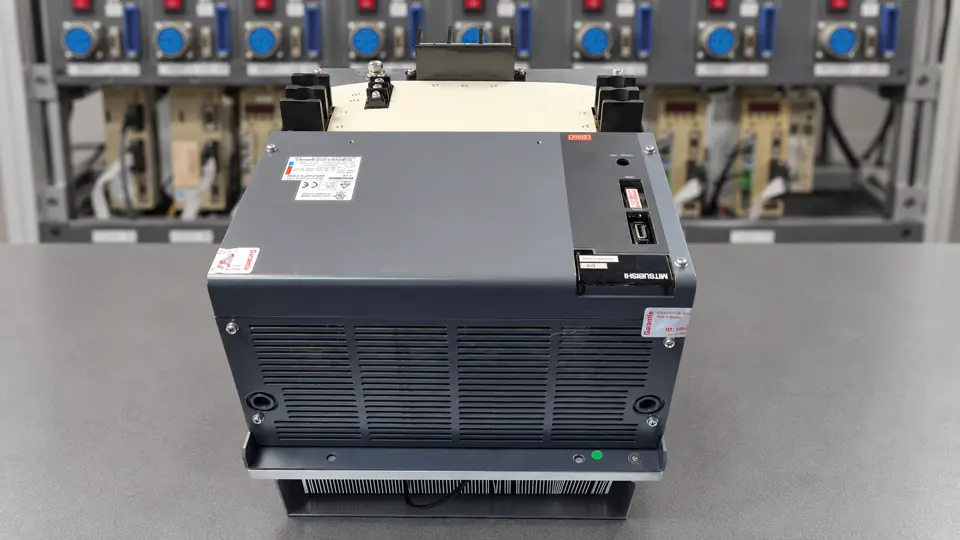 Top view after repair | Mitsubishi MDS-DH-CV-550
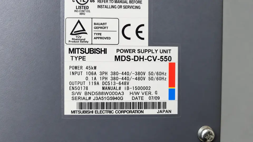 Nameplate | Mitsubishi MDS-DH-CV-550
Request a repair assessment
Send the complete unit designation, a nameplate photograph and the observed fault sequence. industrypart supports repair and preventive overhaul of industrial drive electronics.
Mitsubishi MDS-DH-CV-550 Power Supply Unit
Mitsubishi repair service