26.08.2025 by Viktor Siebert
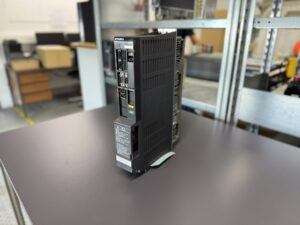
Mitsubishi MDS-D-SP-80 Spindle Drive Unit – Technical Analysis & Repair Insights
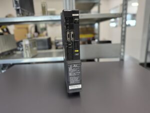
We received the fifth unit of MDS-D-SP-80 from the same customer. Interestingly, all devices came from different machines but failed in a similar way, mostly after weekends.
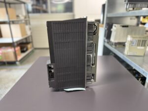
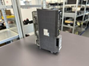
Externally, all units appeared in excellent condition: clean cooling fins, fully functional fans, no signs of dust or dirt. Still, the error pattern was identical:
- Device would not start
- LED display remained dark
- No functionality
Upon opening, we found the power transistor module had exploded. In addition, the driver circuitry was damaged, in some cases with visible burn marks.
Initial analysis raised two questions:
- Were these failures due to a manufacturing defect of the transistor modules?
- Or were aged control signals responsible for triggering module breakdowns?
We carefully examined several failed modules and analyzed the control circuit. The results pointed to age-related degradation:
- Several electrolytic capacitors had lost over 50% of their capacity
- Optocouplers showed heavy wear, with signal strength reduced to about 30%
This imbalance led to unstable gate drive signals, especially when machines were restarted after being idle for several days. The result: catastrophic failure at power-up.
To confirm, we sourced a used reference unit from the same production series. Our engineers compared components, performed detailed measurements, and confirmed the findings: component aging was the root cause.
The repair required:
- Full cleaning
- Preventive replacement of all capacitors and optocouplers
- Replacement of the entire power stage (IGBT module)
- Surface treatment and protective coating
- Final testing and burn-in under load conditions
The repaired drives were then tested on our Mitsubishi CNC test system:
- Long-term load operation
- Thermal endurance runs
- Full monitoring and logging
Result: All repaired units passed flawlessly.
Lesson learned: Simply replacing the exploded module is not enough. Only preventive replacement of all aged parts ensures long-term reliability.
Preventive Measures for Customers
- Regular cleaning of cooling fins and fans
- Fan replacement every 3–5 years
- Periodic insulation tests of motors and cables
- Inspection of seals against oil and moisture ingress
- Preventive overhaul every 8–10 years before catastrophic failures occur
Conclusion
The Mitsubishi MDS-D-SP-80 is a robust spindle drive, but it is prone to failures caused by aging components in the control section. Preventive overhaul and timely component replacement are the best way to avoid costly machine downtime.
To mentioned Mitsubishi Drive: Mitsubishi MDS-D-SP-80 Spindle Drive Unit
More details about our Mitsubishi repair services can be found here:
Mitsubishi drive Repair by Industrypart
📞 Feel free to contact us with any questions about your Mitsubishi drive technology.
Our expert team is happy to help!
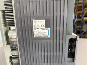
Technical Specifications
| Parameter | Value |
|---|
| Model | MDS-D-SP-80 (Spindle Drive Unit) |
| Power | 7.5 kW (50% ED) |
| Input (DC link) | DC 270–311 V, 20 A |
| Control supply | 0.2 A, 1-phase 200 / 200–230 V, 50/60 Hz |
| Output | 18 A, 3-phase 155 V, 0–833 Hz |
| Standard | EN50178 |
| Manual No. | IB-1500875 |
| Software Ver. | 1501W002 AC |
| Hardware Ver. | Q |
| Date | 10/02 |
| Manufacturer | Mitsubishi Electric Corporation, Japan |
Application Environment & Compatible Equipment
The MDS-D-SP-80 spindle drive is typically used in CNC machine tools, especially turning and milling machines from Mitsubishi, Mazak, DMG Mori and Okuma.
It is designed for medium power spindles (7.5 kW) and ensures precise torque and speed control.
Compatible with:
- Mitsubishi MDS-D control systems
- Various Mitsubishi spindle motors (HF-series, SJ-series)
Functional Description
The spindle drive converts the incoming AC power into a regulated DC link and provides PWM signals for spindle motor control.
Key features:
- High dynamic response for machining operations
- Integrated protection against overcurrent, overvoltage, and overheating
- LED alarm display and diagnostic functions
- Fiber optic communication with the CNC
Alarm Messages and Troubleshooting
| Alarm No. | Description | Cause | Solution |
|---|
| 10 | Insufficient voltage | Input voltage too low | Check power supply |
| 23 | Excessive speed error | Difference between actual and commanded speed | Adjust parameters, reduce load |
| 24 | Grounding | Motor/cable insulation fault | Perform insulation test, replace motor/cable |
| 31 | Overspeed | Exceeded max spindle speed | Verify parameters, check PLG |
| 32 | Power module overcurrent | Overcurrent in IGBT module | Inspect motor, replace module |
| 33 | Overvoltage | DC bus voltage exceeded | Check supply, regenerative resistor |
| 45 | Fan stop | Fan failure | Replace fan, clean system |
| 46 | Motor overheat | Thermal error | Check cooling, motor load |
| 50 | Overload 1 | Overload detected | Reduce cutting load, check parameters |
| 71 | Power supply interruption | Instantaneous voltage drop | Stabilize input power |
Components
| Name | PCB/Module designation | Qty |
|---|
| Control board | RM115A-21 or BC886A028G51 | 1 |
| Power board | RM162C-SP or BC886A010G52 | 1 |
| Power module | BKO-NC1212 H87 or MP04-D-SP-80 | 1 |