07.12.2025 by Viktor Siebert
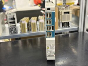
Repair of a Mitsubishi MDS-C1-V2-2003 Servo Drive Unit Without Display and Without Function
When the customer attempted to start their machine on Monday morning, the situation was immediately unusual.
While all other control units powered up correctly, the MDS-C1-V2-2003 servo drive remained completely dark.
No LED activity, no flickering, no reaction to RESET or CNC initialization. This is a classic indication of an internal low-voltage logic failure or a defective startup sequence.
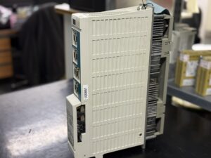
Our incoming inspection always begins with a visual assessment. The unit showed no external impact and no thermal discoloration, which often points to a silent internal defect caused by long-term aging, thermal cycling or oxidation of semiconductor junctions. Such failures commonly appear after a machine has been powered off for a weekend and the components cool down fully.
After removing the housing cover, the internal power bus and the state of the control board were examined. Measurements at the test points revealed that the primary DC bus voltage (270–311 V) was present and stable, indicating the power supply unit was operating normally. However, the regulated low-voltage supplies, including the 5 V and 12 V rails required for the processor and communication logic, were completely absent. When these voltages collapse, the CPU cannot execute its startup routine and the unit remains entirely non-responsive.
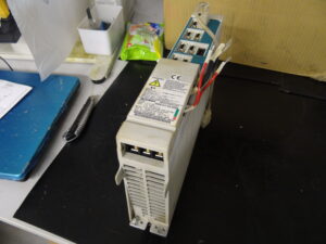
The power stage was then inspected independently. With U/V/W isolated, we measured the IGBT half-bridges and detected abnormal partial conduction in two segments. While not immediately destructive, such conduction prevents the drive from passing its self-test, during which the system checks the integrity of the output stage before enabling any motion. This confirmed that both the logic supply section and parts of the power module had sustained damage.
A complete disassembly of the power board followed. All thermally stressed areas were cleaned and inspected under magnification. Several critical components were removed, individually tested and replaced, including transistor elements in the driver stage, multiple gate resistors and a defective snubber capacitor.
On the control board, the low-voltage power circuitry underwent a full rebuild. All electrolytic capacitors in relevant circuits were replaced, reference voltages recalibrated and communication signal integrity verified.
Following the repair, the unit was transferred to our Mazak-compatible test bench. There we simulate typical axis loads, monitor current flow, track regulation behavior, observe thermal characteristics and evaluate even minor deviations in detector feedback. The drive passed all tests, showing stable internal voltages, correct detector timing and clean motion curves without overshoot or excessive ripple.
Because the C1 series relies heavily on optical CNC communication, extensive integrity testing of the fiber link was also performed under changing load scenarios. The behavior remained fully stable.
The customer ultimately received a fully restored and fully tested unit, eliminating the need for a costly retrofit and preventing extended machine downtime.
Preventive Measures for the Customer
- Regular cleaning of the control cabinet
- Semiannual inspection of all connectors
- Verification of fan function and airflow
- Annual motor insulation testing
- Monitoring of DC bus stability in facilities with power fluctuations
- Preventive replacement of aging capacitors after approximately ten years of operation
Conclusion
This failure was typical for aging effects within low-voltage power regulation and the output stage. By rebuilding the logic supply and the power module, the unit was restored to reliable operation, ensuring continued machine productivity without the cost of a new replacement unit.

To mentioned Mitsubishi Drive: Mitsubishi MDS-C1-V2-2003 Servo Drive Unit
More details about our Mitsubishi repair services can be found here:
Mitsubishi drive Repair by Industrypart
📞 Feel free to contact us with any questions about your Mitsubishi drive technology.
Our expert team is happy to help!
Technical Specifications
| Feature | Value |
|---|
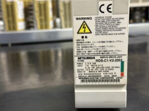
| Type | MDS-C1-V2-2003 |
| Manufacturer | Mitsubishi Electric, Japan |
| Power rating | 2.0 / 0.3 kW |
| Input | 1-phase 200–230 V AC 50/60 Hz, 0.2 A |
| DC bus | DC 270–311 V |
| Output | 3-phase 155 V, 0–240 Hz |
| Control | Mazak / Mitsubishi CNC, MDS-C1 series |
| Cooling | Convection cooling plus internal fan |
| Serial number | JBAG… |
| Manual reference | Mazak MDS-C1 Alarm & Troubleshooting Manual |
Operating Environment and Compatible Equipment
The unit is commonly installed in Mazak CNC machines, including Mazatrol M-Plus, Fusion, Matrix and Smart control generations.
Typical axis assignments: X, Y, Z, B, depending on the machine configuration.
Compatible components include:
- Mitsubishi HF, HA and HC series servomotors (depending on model configuration)
- Power Supply Units MDS-C1-CV / MDS-C1-PS
- CNC linkage via CN1A/CN1B optical communication
- Incremental or absolute feedback devices via CN2/CN3
Functional Description
The MDS-C1-V2-2003 is a Mazak-specific C1-series servo drive.
Its core functions include:
- PWM-based control of the motor’s three-phase output stage
- Handling of encoder feedback and absolute position data
- Processing of detector signals from motor and machine side (CN2 / CN3)
- Power conversion via the internal DC bus
- Monitoring of overcurrent, overvoltage, communication integrity, initialization states and thermal conditions
- Continuous communication with the CNC through fiber-optic channels
C1-series units use a dedicated Mazak alarm logic, meaning that alarms, reset rules and diagnostic steps differ significantly from standard Mitsubishi MDS-B/D drives.
Alarms and Troubleshooting
| Code | Description | Cause | Solution |
|---|
| 10 | Insufficient voltage | DC bus voltage too low | Check supply voltage, contactor function, improve power quality |
| 12 | Memory error | Hardware or RAM fault during power-up | Replace drive, verify environmental conditions |
| 13 | Software processing error | Internal software process not completed | Inspect or replace drive |
| 17 | A/D converter error | Error in current feedback circuit | Replace drive |
| 18 | Initial communication error (main side) | Communication with motor-side detector failed | Check cables, connectors and detector |
| 21 | No signal 2 | No ABZ feedback detected | Inspect detector cable, feedback unit |
| 23 | Excessive speed error | Speed deviation too large | Check parameters, reduce mechanical load |
| 24 | Grounding | Motor U/V/W shorted to frame ground | Perform insulation test, replace motor or cable |
| 31 | Overspeed | Motor speed over allowable limit | Inspect load conditions, PLG waveform |
| 32 | Power module overcurrent | Overcurrent detected in power module | Check motor wiring, insulation and replace drive if needed |
| 33 | Overvoltage | DC bus voltage above tolerance | Inspect regeneration circuit, verify supply quality |
Components
| Assembly | Part number / Code | Function | Notes |
|---|
| Control board | RK112A-22 or BN634A980G51 | Control logic, CNC communication | No display in case of failure, startup faults |
| Power board | RL122B-V2 or BN638A153G51 | PWM output stage, current regulation | Frequent failure point under overload |
| Power module / IGBT stack | BKO-NC1207 H04 or A2-V2-2003 | Conversion DC to AC, motor drive output | Short circuits cause immediate shutdown |