30.09.2025 by Viktor Siebert
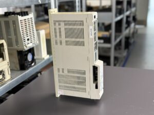
Repair Case: Mitsubishi MDS-B-V1-03 Servo Drive Unit with Alarm 3A (Overcurrent)
Initial Situation.
A customer contacted us with a critical problem: their CNC machine repeatedly failed during rapid load changes. The Mitsubishi MDS-B-V1-03 servo drive unit was shutting down unexpectedly, and the CNC controller displayed Alarm 3A Overcurrent.
At first, the failure seemed sporadic, but with every high-dynamic movement the machine stopped abruptly. This type of fault is especially dangerous in production environments, as it can lead to axis crashes, tool breakage, or even long machine downtimes.
Failure Analysis
Once the unit arrived in our workshop, we carried out a structured diagnostic process.
- A visual inspection already revealed signs of aging: the electrolytic capacitors in the DC link section were visibly swollen.
- The ESR values of the capacitor bank were significantly above acceptable limits, a clear indicator that they had lost most of their buffering capacity.
- Furthermore, optocouplers and ISO amplifiers showed unstable switching characteristics during oscilloscope testing, resulting in delayed or distorted signal transmission.
- Several ICs on the control board displayed irregular behavior, especially under temperature variation.
In summary, the drive was no longer capable of handling high dynamic current flows. During rapid acceleration and deceleration phases, the power stage would go into overcurrent shutdown. If the unit had continued to run in this condition, there would have been a high risk of permanent motor damage or even cascading failures in the CNC control system.
Repair Process
The repair followed our established procedures with strict documentation and checklists.
- Cleaning & Preparation
The drive was completely disassembled. All components were cleaned in an emulsion bath to remove dust, oil residues, and conductive particles. Afterward, the boards were dried in a controlled oven to avoid moisture-related insulation problems.
- Component Replacement
- The entire electrolytic capacitor bank in the DC link was replaced with high-quality, long-life capacitors.
- All critical optocouplers, ISO amplifiers, and aging ICs were renewed.
- Several power semiconductors in the drive stage were exchanged as a preventive measure, even though they still tested within specification.
- Solder joints on heat-stressed areas were reinforced to guarantee mechanical and electrical reliability.
- Verification of Circuit Integrity
PCB traces in the power section were carefully inspected. Some had slight discoloration from thermal stress and were resoldered or reinforced where necessary.
- Reassembly & Safety Tests
After reassembly, the unit underwent an insulation test (HiPot) as well as grounding verification to ensure operator safety. All connectors and fastening points were secured to factory torque values.
Test Procedures
The repaired unit was tested extensively on our in-house servo drive test bench:
- Dynamic acceleration and deceleration cycles were simulated.
- High-frequency load changes were introduced to replicate real machine conditions.
- The thermal response of the drive was monitored during six hours of continuous operation under maximum rated load.
- Signal integrity was observed at multiple test points to verify correct feedback from the encoder interface.
The unit passed all test stages without a single recurrence of the overcurrent alarm.
Customer Benefit
After the repair, the servo drive was fully functional again and returned to the customer with a detailed test protocol. The intervention not only restored machine availability but also prevented serious secondary damage. If the customer had continued operating the faulty unit, the risk of an axis crash, broken tools, or a complete machine standstill would have been extremely high.
By renewing critical components and carrying out preventive replacements, the service life of the MDS-B-V1-03 was extended considerably. This approach saves costs compared to purchasing a new drive, reduces machine downtime, and supports sustainable use of industrial electronics.
Conclusion
This repair demonstrates how failures in industrial drives often stem from aging components rather than catastrophic design flaws. Systematic diagnostics, professional repair procedures, and thorough testing ensure reliable operation and protect customer investments. Preventive maintenance, such as capacitor replacement and fan inspections, is the key to long-term machine safety and availability.
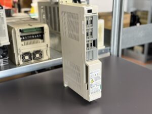
To mentioned Mitsubishi Drive: Mitsubishi MDS-B-V1-03 Servo Drive Unit
More details about our Mitsubishi repair services can be found here:
Mitsubishi drive Repair by Industrypart
📞 Feel free to contact us with any questions about your Mitsubishi drive technology.
Our expert team is happy to help!
Technical Specifications
| Feature | Value |
|---|
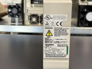
| Manufacturer | Mitsubishi Electric Corporation, Japan |
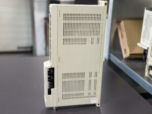
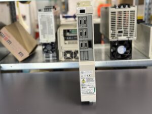
| Device Type | MDS-B-V1-03 Servo Drive Unit |
| Rated Power | 0.3 kW |
| Input DC Bus | DC 270–311 V |
| Internal Power Supply | AC 1 Phase 200 or 200–230 V 50/60 Hz |
| Motor Output | 2.9 A, 155 V, up to ±240 Hz |
| Manual Reference | BNP B3759 |
| Production Date | 09/09 |
| Software | VE0101 |
| Other | UL CE certified |
Application Environment & Compatible Devices
- Typical Machines: CNC machine tools, machining centers, milling and turning machines.
- Controllers: Mainly Mitsubishi Meldas-B and Meldas-C controllers.
- Compatible Motors: Mitsubishi AC servo motors of the HA, HF, and HC series with matching encoders.
- Application Areas: Axis positioning, high-precision motion control, machining processes with fast load changes.
Functional Description
The MDS-B-V1-03 is a servo drive unit designed to control AC servo motors up to 0.3 kW.
- Provides motor control (current, position, and speed regulation).
- Handles feedback signals from encoders (incremental or absolute).
- Built-in protection functions against overcurrent, overspeed, and overheating.
- Communicates with Mitsubishi CNC controllers via internal interfaces.
- Optimized for dynamic load changes thanks to robust power stages and fast signal processing.
Alarm Messages & Troubleshooting
| Code | Error Description | Cause | Solution |
|---|
| 11 | Axis Selection Error (ASE) | Incorrect rotary switch setting | Check axis parameters and correct setting |
| 12 | Memory Error (ME) | Fault in SRAM or FROM | Check/replace memory components |
| 13 | Software Processing Error | Processing not completed in time | Restart control, check CPU |
| 16 | RD Position Detection Error | Faulty feedback signals | Check encoder and wiring |
| 18 | AD Converter Error | A/D converter malfunction | Check/replace control board |
| 1A | STE1 Serial Detector Error | Initialization failed | Inspect wiring and encoder |
| 1B | CPU Error (SUB) | EEPROM data invalid | Check/replace control board |
| 31 | Overspeed | Motor speed > 1.2 × rated speed | Check load and control |
| 32 | Power Module Overcurrent | Overcurrent in power stage | Check DC link, inspect power transistors |
| 3A | OC Overcurrent | Excessive motor current | Inspect motor, perform insulation test |
Components
| Component | Board designation | Qty |
|---|
| Control Board | RK111B-11 or BN634A815G51 D | 1 |
| Power Board | RK155B-V1-03 or BN634AB10G51 B | 1 |
| Heatsink | Aluminum with mounted fan | 1 |
| Fan | 24V DC axial fan | 1 |
| DC Link Capacitors | Electrolytic capacitor bank | 1 |
| Connectors | CN1, CN2, encoder inputs, power terminals | several |