24.09.2026 by Viktor Siebert
Mitsubishi MDS-B-SVJ2-20 with intermittent Alarm 10: systematic diagnosis of DC bus undervoltage
The Mitsubishi MDS-B-SVJ2-20 arrived with a fault that occurred only intermittently in the machine. The axis initially operated, but repeatedly stopped with Alarm 10. Intermittent undervoltage faults of this kind are challenging in practice. A unit may execute several movements correctly after power up and then stop suddenly because of a brief voltage dip, main contactor switching, acceleration or increasing temperature. A visual inspection or short no load test is not sufficient in such a case.
The first step was to identify the alarm unambiguously. On the MDS-B-SVJ2, Alarm 10 indicates insufficient voltage in the PN bus. The monitor responds when 200 V or less is detected while Servo Ready is active. It was therefore clear that the investigation could not be restricted to the power module. The complete chain from the three phase supply through protective devices, contactor, terminals and internal rectification to DC bus measurement had to be included in the diagnosis.
The rating plate was documented before the unit was opened. The unit is designed for 3 phase AC 200 to 230 V at 50 or 60 Hz. The main circuit is rated at 12.8 A, the control circuit at 0.3 A and the output at 14 A. The production date of 1998/10 also shows that the servo amplifier has operated in an industrial environment for many years. With equipment of this age, time dependent changes in capacitors, relays, connectors, solder joints and fans must always be considered. Age alone, however, is not proof of a defective component.
The initial checks addressed possible machine side causes. They included measuring all three input phases, checking for a momentary open phase, observing the voltage as the contactor switched and inspecting CN3 and the related contactor control. A contact may show good continuity without load and still develop excessive contact resistance under load. Testing should therefore be dynamic wherever possible. It is also necessary to determine whether other loads connected to the same supply section cause a voltage dip when they are switched on.
The drive was then opened and professionally cleaned. Dust can impair cooling and, together with moisture, create conductive deposits. After cleaning, connectors, screw terminals and board areas were inspected visually. Particular attention was paid to control board J2B-C13C, power boards RK822A-6 and RK822C-6 and load capacitor board RK823Z. In the undervoltage monitor, the large DC bus components are not the only relevant parts. Auxiliary supplies, relay contacts, measuring resistors, galvanically isolated signal paths and solder joints are equally important because faulty acquisition can trigger the same alarm as a genuine voltage dip.
The capacitors were not judged merely by their external appearance. An electrolytic capacitor can look normal while having lost capacitance or developed increased ESR. Under load, this produces greater DC bus ripple. The smaller capacitors in the internal supplies are also important because unstable auxiliary voltages can affect measuring and control logic. The relevant contact and relay paths and any suspicious solder joints were also inspected. The components that actually require replacement must be selected only after these findings are available. The information supplied does not prove the replacement of a specific component, and no such replacement is therefore claimed here.
For the functional test, the servo amplifier was not merely powered at no load. A meaningful test must reproduce the operating states in which the fault occurs at the customer’s machine. This includes repeated power cycling, Servo Ready cycles, acceleration and deceleration, different speeds and extended running times. The input phases and DC bus voltage are monitored throughout. Output currents, motor detector signals, enables and temperature development are observed at the same time. A thermal test is particularly important for an intermittent fault because contact resistance, relays and aged electronic components can change their behaviour as temperature rises.
The unit is operated on a suitable Mitsubishi test system with a compatible original motor. This verifies the interaction of communication, detector acquisition, current control, motor drive and protective functions. Load changes are particularly important because a weak supply or unstable DC bus often becomes apparent only during rapid acceleration. The test should continue for several hours and include multiple cold and warm starts. Only if Alarm 10 does not reappear under these conditions and the measurements remain stable can the repair be regarded as technically substantiated.
For the customer, clean separation of machine and drive causes is essential. Replacing only the amplifier while a worn main contactor, loose terminal or open phase remains in the machine can cause the replacement unit to report Alarm 10 as well. Conversely, stable mains voltage at the control cabinet does not rule out an internal drive fault. Measurements must therefore be made at the correct points and at the correct time. Information on whether the alarm occurs during power up, acceleration, after an extended running period or together with other loads is particularly valuable.
This case demonstrates why intermittent undervoltage alarms require a systematic approach. The alarm number describes the detected condition, but it does not automatically identify the defective component. Only the combination of manual analysis, measurement of the external supply, inspection of internal assemblies and a realistic long term test produces a dependable diagnosis. This prevents unnecessary component replacement and increases the likelihood that the axis will remain reliably available after repair.
Preventive measures for the customer
- Inspect control cabinet filters and fans regularly and clean them at least every six to twelve months depending on the environment.
- Check the internal fan of the MDS-B-SVJ2-20 for reliable starting, airflow and bearing noise. Replace it preventively if ageing is evident.
- Measure mains voltage not only at no load, but also while the main contactor switches and while the machine is under high load.
- Inspect contactor, relays, terminals and CN3 for heating, oxidation, loose contacts and voltage drop.
- Record the alarm history. Time, machine state, axis movement and temperature are extremely helpful with intermittent faults.
- Route motor and detector cables separately from interfering power cables and check grounding.
- For units from the 1990s, plan a preventive inspection of capacitors, fans, relays and solder joints before an unplanned failure occurs.
- After switching off, wait at least 15 minutes, confirm that the CHARGE indicator is off and measure the voltage between P and N. Work must be carried out only by qualified personnel.
Conclusion
Alarm 10 on the Mitsubishi MDS-B-SVJ2-20 is a PN bus undervoltage message. If it occurs intermittently, both the external mains and contactor chain and age related faults inside the servo amplifier must be considered. Reliable repair therefore requires dynamic measurements, targeted assembly testing and a test lasting several hours with an original motor. This significantly reduces the risk of another machine shutdown.
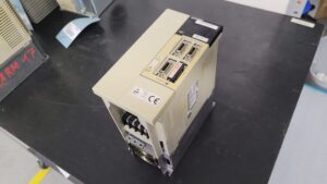
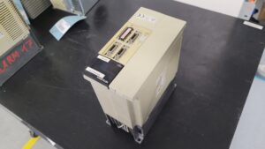
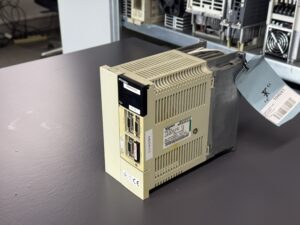
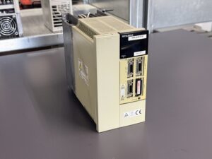
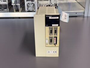
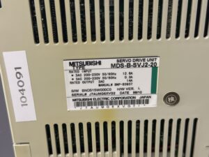
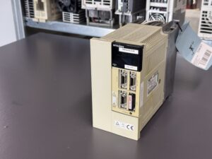
To mentioned Mitsubishi Drive: Mitsubishi Servo Drive Unit MDS-B-SVJ2-20
More details about our Mitsubishi repair services can be found here:
Mitsubishi drive Repair by Industrypart
📞 Feel free to contact us with any questions about your Mitsubishi drive technology.
Our expert team is happy to help!
Technical specifications
| Feature | Value |
|---|
| Manufacturer | Mitsubishi Electric Corporation, Japan |
| Device type | AC Servo Drive Unit, MELDAS MDS-B-SVJ2 series |
| Model | MDS-B-SVJ2-20 |
| Capacity class | 2.0 kW |
| Rated main circuit input | 3 phase AC 200 to 230 V, 50/60 Hz, 12.8 A |
| Rated control circuit input | AC 200 to 230 V, 50/60 Hz, 0.3 A |
| Permissible input voltage range | 3 phase AC 170 to 253 V according to the manual |
| Rated output | 3 phase AC, 14 A |
| Control method | Sine wave PWM, current control method |
| Communication and control | MELDAS CNC communication via CN1A and CN1B, external signals via CN3 |
| Protective functions | Overcurrent, overvoltage, overload, motor overtemperature, detector error, regeneration error, undervoltage, instantaneous power failure, overspeed and excessive error protection |
| Cooling | Forced cooling by an internal fan |
| Protection class | IP20 |
| Dimensions | 90 x 168 x 195 mm, excluding required wiring and cooling clearances |
| Weight | 2.0 kg |
| Operating environment | 0 to 55 °C, maximum 90% relative humidity, no condensation |
| Production date of the shown unit | 1998/10 |
| Hardware version | L |
| Manual reference | BNP-B3937, MDS-B-SVJ2 Series Specifications and Instruction Manual |
The input and output data were taken from the rating plate of the unit shown. The dimensions, weight, environmental conditions, control method and protective functions were taken from Mitsubishi manual BNP-B3937.
Application environment and compatible equipment
The MDS-B-SVJ2-20 is a single axis servo amplifier for older Mitsubishi MELDAS CNC systems. Typical applications include machining centres, lathes, milling machines and other machine tools in which feed axes must be controlled precisely. The drive processes command values from the CNC, supplies the servomotor via U, V and W and simultaneously evaluates the motor detector feedback.
Depending on speed, detector version and permissible output limitation, the Mitsubishi manual specifies motors from the HC, HC-R, HC-SF, HC-RF and HA-N series. Combinations for the MDS-B-SVJ2-20 include HC152, HC153, HC202, HC203, HC352, HC-SF352, HC-SF353 and HC-RF203. A combination marked with an asterisk uses a motor with an amplifier one capacity class lower, which limits the output characteristics. Before replacing a unit, the motor code, detector type, parameters, brake and machine approval must therefore be checked against the documentation for the specific machine.
Functional description
The MDS-B-SVJ2-20 converts the three phase mains supply into a regulated DC bus voltage. From this PN bus, the power stage generates motor phases U, V and W by means of a pulse width modulated output stage. Current control ensures that the torque requested by the CNC system is built up quickly and in a controlled manner. Position and speed information is supplied by the motor detector via CN2. CNC communication uses CN1A and CN1B. CN3 integrates external enable, contactor and brake functions.
The control system monitors motor current and position as well as DC bus voltage, power stage, regeneration, temperature, communication and detector signals. If a dangerous or implausible operating condition is detected, the amplifier stops the axis by controlled deceleration or dynamic braking and reports the corresponding alarm to the CNC.
Alarm 10 is an undervoltage message. According to the manual, it is detected in the Servo Ready state when the PN bus voltage falls to 200 V or less. In the case of an intermittent fault, it is therefore not sufficient to measure the mains voltage once at no load. The decisive question is whether the supply, contactor, contacts and internal voltage processing remain stable during switching, acceleration and thermal load.
Alarm messages and troubleshooting
| Code | Fault description | Possible cause | Test and remedy |
|---|
| 10 | Undervoltage, PN bus 200 V or less at Servo Ready | Open phase, low mains voltage, insufficient supply capacity, contactor or contact fault, faulty CN3 or relay | Test all three phases dynamically, inspect CN3 and cable, test contactor and drive relay under load, inspect internal detection and DC bus |
| 13 | Software processing error 1 | CPU peripheral circuit fault or adverse environment | Check repeatability, grounding and temperature, inspect control board |
| 15 | Memory error 2 | Self diagnosis fault in CPU peripheral circuit | Check LED display and repeatability, inspect control board |
| 17 | A/D converter error | CPU peripheral or analogue acquisition fault | Check grounding, temperature and internal measuring circuits |
| 18 | No initial communication with motor detector | CN2 disconnected, detector cable open, detector or input circuit faulty | Isolate the cause using CN2, cable, detector and a comparison axis |
| 24 | Ground fault | Ground fault in U, V or W, motor fault | Test motor cable and motor separately, locate insulation fault |
| 25 | Absolute position data lost | Low battery voltage, open battery wire or connector | Check battery and wiring, remove the cause before establishing the position again |
| 30 | Over regeneration | Incorrect resistor, incorrect SV036 parameter, high mains voltage | Check regeneration power, resistor, mains voltage and parameter |
| 31 | Overspeed | Parameter error, overshoot, detector fault | Check motor and axis parameters, gain, acceleration ramp and detector |
| 32 | Power module overcurrent | Short circuit or ground fault in motor cable, amplifier fault | Isolate motor and cable, test power stage statically and dynamically |
| 33 | Overvoltage | High mains voltage, faulty regenerative resistor or connection | Measure mains and DC bus, inspect regenerative circuit |
| 34 | NC-DRV CRC communication error | Cable, terminator, battery unit, grounding, drive or CNC faulty | Isolate communication path and grounding systematically |
| 36 | NC-DRV communication interrupted | CN1A or CN1B disconnected, broken cable | Inspect connectors and cable continuity |
| 3A | Overcurrent | Excessive gain, incorrect motor phases, grounding fault, faulty drive or detector | Check parameters, U/V/W assignment, grounding, drive and detector |
| 3C | Regeneration circuit error | Faulty resistor or regenerative transistor, stopped fan and overheating | Check resistor and transistor, inspect fan operation particularly on SVJ2-20 |
| 50 | Overload 1 | Motor capacity insufficient, brake does not release, stiff mechanics, unsuitable parameters | Check load current, brake, mechanics and SV021/SV022 |
| 52 | Excessive error 1 | Gain too low, excessive load, blocked brake, low input voltage | Check supply under load, mechanics, brake and control parameters |
| 88 | Watchdog | Internal amplifier fault or inadequate grounding | Check grounding and repeatability, repair control electronics |
Important: Work on the DC bus may only be carried out by qualified personnel. After power is switched off, Mitsubishi requires a waiting time of at least 15 minutes. The CHARGE indicator must then be confirmed off and the voltage between P and N must be checked with a suitable meter.
Components
| Assembly | Designation or code | Function | Test or repair notes |
|---|
| Control board | J2B-C13C | Communication, control, protective logic and signal evaluation | Check supply voltages, connectors, solder joints, reference voltages and alarm recording |
| Power boards | RK822A-6 and RK822C-6 | Drive and connection of the power stage | Check driver stages, galvanic isolation, solder joints and ageing components |
| Load capacitor board | RK823Z | Smoothing and stabilisation of the DC bus | Check capacitors, discharge path, contacts and behaviour under load |
| Power stage | Mitsubishi power module | Generation of motor phases U, V and W | Check for short circuit, insulation fault, gate drive and thermal behaviour |
| Cooling | Internal fan and heatsink | Dissipation of power losses | Check airflow, bearing noise, speed, contamination and temperature |
| Connection area | L1/L2/L3, L11/L21, U/V/W, P/N/C/D, CN1A, CN1B, CN2 and CN3 | Power supply, motor, communication, detector and external signals | Check screw connections, connector retention, oxidation, broken cables and correct assignment |