26.10.2025 by Viktor Siebert
Repair of a Mitsubishi MDS-B-SP-37 Spindle Drive Unit
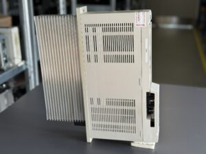
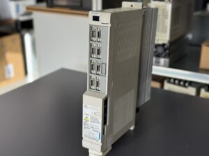
The submitted Mitsubishi MDS-B-SP-37 Spindle Drive Unit arrived with a brief but critical customer statement: “Display is black, and the machine will not start.”
A short description that often hides a complex underlying issue. When a spindle drive shows no display or status lights, the cause is rarely trivial, it usually indicates a failure deep within the unit’s internal power distribution or control logic.
During the initial inspection at our test facility, the device showed no visible activity, no LED response, no relay activation, no indication of startup. The 200 V AC input was present, and the DC link voltage charged correctly. This confirmed that the main power section was functioning, but the internal control logic remained completely unresponsive.
After removing the housing and performing a detailed visual inspection, our technicians began a structured diagnostic process. With older Mitsubishi MDS-B series drives, it is essential to proceed step by step: first verify the power section, then the auxiliary supply, and finally the control logic. The investigation quickly pointed toward the RK311B control board, responsible for the entire logic and communication management within the drive.
The first measurements revealed that the auxiliary voltages of +5 V and +15 V were no longer stable. As a result, the microcontroller and memory could not initialize properly. This type of failure is common in units that have operated for years under continuous heat load, aging components in the low-voltage supply lose stability and eventually prevent startup.
The device was then completely disassembled, cleaned, and processed according to our preventive repair procedure. At our facility, repairs are never limited to replacing the failed component alone. Instead, we replace all parts that are known to degrade over time, ensuring long-term stability and avoiding repeat failures. This philosophy preventive refurbishment instead of minimal repair, defines our quality approach.
Our standard procedure includes:
- Replacement of all electrolytic capacitors in both power and control sections to ensure stable supply voltages.
- Verification of the gate driver signals for the IGBT section to confirm symmetry and timing.
- Insulation and high-voltage testing of the DC link to detect possible leakage currents.
- Replacement of fan units to maintain proper cooling and airflow.
- Cleaning of all air ducts and inspection of temperature sensors to prevent heat buildup caused by oil mist or dust.
After the repair, each drive passes through a multi-phase testing process designed to confirm full reliability:
- No-load startup test:
The drive is connected to our Mitsubishi test bench, where power is applied gradually while monitoring all internal voltages and signals using oscilloscopes. Only after stable values are confirmed, the control logic is enabled for functional testing.
- Full-load test:
The drive operates with a reference spindle motor under rated load conditions. During this test, speed, current, and temperature curves are recorded while simulating real CNC commands such as acceleration, deceleration, and braking cycles. The repaired MDS-B-SP-37 performed precisely and without instability.
- Long-term burn-in test:
Finally, the drive undergoes several hours of cyclic thermal load at elevated temperature. This stage is critical to ensure that no hidden thermal or electronic degradation remains. Only drives that pass this phase flawlessly receive the final approval certificate.
Special attention is always given to communication integrity between the CNC and drive. Even when the display works again, residual errors such as CRC or ADE (A/D conversion) faults can indicate deeper logic issues. Therefore, all encoder signals and communication ports are tested as part of the final inspection.
After the entire test sequence, the MDS-B-SP-37 was documented in detail including measurements, serial numbers, and board configuration (RK311B control board, RK121C-SP-37 power board). The drive passed all functional and thermal tests and was released for return to the customer.
Conclusion
A black display on a Mitsubishi spindle drive is rarely a coincidence. It almost always points to a failure in the internal low-voltage supply or control circuitry. Through structured diagnostics, preventive replacement, and thorough multi-phase testing, the operational lifespan of these units can be extended significantly.
For many MDS-B series models that are now discontinued, professional refurbishment is the most reliable and sustainable solution. Our process ensures that every returned drive is not only working but also qualified for continuous industrial use tested, documented, and ready for many more years of service.
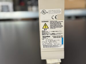
To mentioned Mitsubishi Drive: Mitsubishi MDS-B-SP-37 Spindle Drive Unit
More details about our Mitsubishi repair services can be found here:
Mitsubishi drive Repair by Industrypart
📞 Feel free to contact us with any questions about your Mitsubishi drive technology.
Our expert team is happy to help!
Technical Specifications
Overview
The Mitsubishi MDS-B-SP-37 is a spindle drive from the proven MDS-B series, designed for high-speed and high-precision machining operations. This compact 3.7 kW unit is widely used in vertical and horizontal CNC machining centers, providing stable torque control, dynamic performance, and high reliability for industrial applications.
- Device category: Spindle Drive Unit
- Series: MDS-B (200 V class)
- Construction: Compact, forced-air cooled, service-friendly
- Function: Controls the spindle axis with torque, speed, and position regulation
Technical Data
| Parameter | Specification |
|---|
| Model | MDS-B-SP-37 |
| Output power | 3.7 kW |
| Input voltage | 200–230 V AC, 50/60 Hz |
| Input current | 17 A |
| Output current | 15 A |
| DC link voltage | 270–311 V DC |
| Protection class | IP20 |
| Country of manufacture | Japan |
| Manufacturer | Mitsubishi Electric Corporation |
Main Components
| Component | Board designation | Quantity |
|---|
| Control board | RK311B or BN634A817G51 | 1 |
| Power board | RK121C-SP-37 | 1 |
| Power stage | Power module (IGBT + DC link section) | 1 |
Typical Alarms and Error Codes
Based on the Alarm and Warning Table (Manual IV-57) for the MDS-A/B-SP series:
| Code | Description | Meaning | Recommended Action |
|---|
| 12 ME1 | Memory Error 1 | Checksum or RAM error detected in control section | Inspect control board, reinitialize if necessary |
| 13 SWE | Software Process Error | Internal process not completed within time limit | Check firmware or CPU section |
| 17 ADE | AD Error | ADC circuit malfunction at initialization | Inspect analog signal path |
| 21 NS2 | No Signal (Spindle Encoder) | No encoder feedback detected | Check encoder cable and signal levels |
| 31 OS | Overspeed | Spindle speed exceeded limit | Verify speed control loop |
| 32 PMOC | Power Module Overcurrent | Overcurrent detected in power section | Inspect IGBT module, check insulation and motor cables |
| 34 DP | CRC Error | Communication error with CNC | Check communication wiring and connectors |
| 40 KE1 | TK Unit Change Error | Abnormal TK unit switching | Verify control parameters |
| 46 OHM | Motor Overheat | Motor thermal sensor triggered | Check cooling, inspect thermal protection circuit |
| 82 NSP | Power Supply No Signal | No feedback from power supply section | Check DC bus and auxiliary voltage lines |