05.08.2025 by Viktor Siebert
Our Repair Story: A Mitsubishi HA33NCB‑TSD5 with a Defective Brake and Encoder
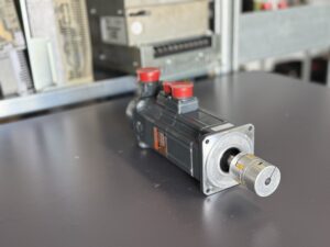
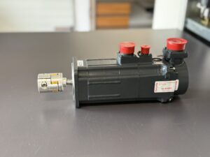
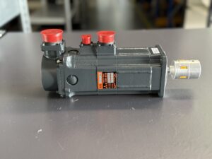
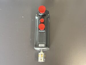
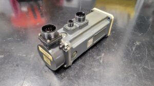
The Mitsubishi HA33NCB‑TSD5 is a robust servo motor with low inertia, an absolute encoder OSA104S2 and an electromagnetic holding brake UA‑0.2‑13. This unit usually operates together with the MDS‑C1‑V2‑0303 drive module. In our example, a failed brake and a damaged encoder caused a machine stoppage. The prices for new parts are considerable: a new brake costs around €1000, and a new encoder about €2700. Replacing all components would not be economical. We show how a worthwhile overhaul can still be achieved.
Initial Situation and Fault Analysis
The motor in question displayed drive alarm codes and jerky movements. The first goal was precise fault localisation. We connect the motor to a compatible Mitsubishi drive, read the alarm codes and check the cable connections. The motor is then mechanically uncoupled so that it can run without load. Tests at different speeds reveal whether the fault is mechanical or electrical. Poor running often indicates worn bearings; an overload alarm on an unloaded motor points more to winding or brake damage. We measure the insulation of the windings, and for encoder problems we check the signals with an oscilloscope and meter, as the manufacturer also recommends. The visual inspection includes opening the encoder chamber to rule out contamination. Once the brake and encoder have been identified as the cause of the fault, we decide to overhaul them rather than opt for costly replacements.
Disassembly, Cleaning and Basic Overhaul
A thorough repair begins with completely dismantling the motor. After removing the end cap, encoder and brake, the rotor is taken out. All components are carefully cleaned: old lubricants, oils and paint residues are removed, chips and dust are rinsed away. The housing parts are degreased, sand‑blasted and prepared for repainting. Bearings and seals are always replaced regardless of their condition, preventing later bearing damage and leaks. During cleaning we also check the electrical insulation of the windings to ensure that no short circuits are present.
Overhauling the Brake and Encoder
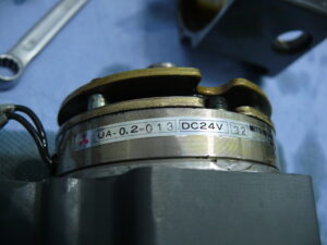
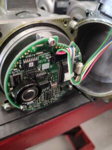
The expensive assemblies brake and encoder are not replaced but overhauled. This know‑how in refurbishment is the result of many years’ experience and makes the repair economical.
Assembly, Test Run and Final Inspection
After overhaul all components are reassembled. New bearings are pressed onto the shaft, the windings are carefully installed and the rotor is centred. The brake and encoder are connected and the motor receives a new coat of paint. On our test bench, which simulates a complete Mitsubishi CNC axis, the motor is put into operation. We check the correct encoder connection, alarm states, speed control and current consumption. Temperature, vibration and noise level are monitored to ensure the motor remains stable under full load. Long‑term tests reveal thermal issues; afterwards we make final adjustments to the control parameters. All results are documented in a test protocol and coordinated with the customer.
Conclusion and Benefits for the Customer
Thanks to this systematic approach the HA33NCB‑TSD5 with defective brake and damaged encoder could be restored to a technically perfect condition. By overhauling the expensive assemblies there was a significant cost saving compared with replacement. At the same time new bearings, seals and thorough cleaning extended the motor’s service life. Our experience with Mitsubishi servo drives, the availability of test rigs and spare parts and the know‑how for refurbishing brake and encoder are decisive for a successful repair. Customers benefit from short downtimes, lower costs and a sustainable use of resources.
Further information such as pricing and delivery times for the mentioned device:
Mitsubishi HA33NCB-TSD5 AC Servo Motor with Encoder
You can find more information about our Mitsubishi repair services here.
📞 Feel free to contact us if you have any questions regarding your drive technology. Our experienced team is always available to support you with advice and assistance.
Device Data
| Parameter | Value / Description | Notes |
|---|
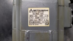
| Model | Mitsubishi HA33NCB‑TSD5 AC servomotor – N‑type (low inertia) with T‑S‑D5 suffix (T = tapered shaft, S = oil seal at shaft end, D5 = IP65 protection) and OSA104S2 encoder plus holding brake UA‑0.2‑13 (24 V DC) | The model number appears on the motor nameplate. In the model configuration, “D5” indicates IP65, “T” refers to a tapered shaft and “S” indicates an oil seal at the shaft end. |
| Input voltage/current | 3‑phase AC 159 V, 2.8 A | The nameplate shows “INPUT 3AC 159 V 2.8 A”. |
| Output power | 450 W (0.45 kW) | The nameplate lists “OUTPUT 450 W”. The specification table assigns the model HA33N a rated power of 0.45 kW. |
| Rated / max torque | Rated torque ≈ 1.43 N·m, stall ≈ 2.94 N·m, max ≈ 10.2 N·m | The servo motor specification table for 3000 r/min models lists for HA33N a rated torque of 1.43 N·m, stall torque of 2.94 N·m and a maximum torque (for drive combinations) of 10.2 N·m. |
| Speed | 3000 r/min (rated speed) | The table assigns the model HA33N a rated speed of 3000 r/min and the nameplate shows “3000 r/min”. |
| Motor inertia | Jm ≈ 1.96 × 10⁻⁴ kg·m² (without brake), Gd ≈ 7.84 × 10⁻⁴ kg·m² (with brake) | The specifications list inertia (Jm) of 1.96 × 10⁻⁴ kg·m² without brake and inertia (Gd) of 7.84 × 10⁻⁴ kg·m² with brake. |
| Weight | 4.5 kg (without brake), 5.5 kg (with brake) | The table indicates a HA33N motor weight of 4.5 kg without brake and 5.5 kg with brake. The nameplate confirms a weight of 5.5 kg. |
| Electromagnetic brake | UA‑0.2‑13 (24 V DC), holding torque ≈ 5.9 N·m, power consumption 15 W | The equipment list gives a 24 V DC brake with 15 W and 5.9 N·m for the HA33N motor. The UA‑0.2‑13 brake is commonly used in Mitsubishi drives. |
| Protection class | IP65 | The suffix “D5” indicates IP65 in the model configuration; the nameplate also indicates IP65. |
| Encoder | OSA104S2 – absolute pulse coder with high resolution; typically 100 000 pulses per revolution | The motor outline emphasises that MDS‑A‑Vx/B‑Vx servos include a high‑precision 100 000‑pulse detector. The OSA104S2 is an absolute pulse coder for HA/HN motors and delivers absolute position data. |
| Shaft form | Tapered shaft with oil seal | In the model configuration the symbol “T” denotes a tapered shaft and “S” denotes an oil seal type. |
| Radial load capacity | 25 kg (straight shaft); 40 kg (tapered shaft) | The table gives a permissible radial load at the shaft end of 25 kg (straight shaft) and 40 kg (tapered shaft) for HA33N. |
Operating environment and compatible devices
The HA33NCB‑TSD5 servomotor is designed for Mitsubishi MDS‑A‑Vx and MDS‑B‑Vx servo systems used in CNC machines of the M300/M500 series. In these systems the power supply and amplifier are separate units, and the motor is driven by Mitsubishi servo amplifiers such as MR‑J2S, MR‑J3 or MDS‑B‑SV. A high‑resolution absolute encoder (100 000 pulses per revolution) provides accurate position feedback, and the motor connects via a main power Cannon plug and a separate detector plug. All HA motors include an oil seal at the shaft end and an integrated thermal protection wire in the detector connector.
The allowable ambient temperature is 0 – 40 °C; the motor must be operated dry and free of oil and water and should not be exposed to condensation. It is protected to IP65, making it resistant to dust and water jets. A tapered shaft with keyway allows connection to precision gearboxes, ball screws or spindles. The 24‑V DC holding brake locks the axis safely in position when power is lost. Typical applications include CNC machine tools, industrial robots, pick‑and‑place machines and other positioning tasks requiring quick acceleration and accurate repeatability.
Function description
An AC servomotor is a rotary electro‑mechanical actuator that provides precise position, speed and torque control. The HA33NCB‑TSD5 has a three‑phase stator winding and a rotor fitted with high‑energy permanent magnets. A OSA104S2 absolute encoder measures the rotor position at high resolution; the built‑in thermal protector and oil seal shield the interior from overheating and contamination. The low inertia allows rapid acceleration and deceleration, while the 24 V DC holding brake locks the shaft when the amplifier is turned off. A servo amplifier processes command and feedback signals, controls the motor current and generates the required speed/torque commands. The tapered shaft (suffix “T”) enables backlash‑free coupling to spindles or planetary gear units.
Alarm messages and troubleshooting
The following table summarises common error codes of the Mitsubishi MDS‑C1‑V2‑0303 servo amplifier used with the HA33NCB‑TSD5 motor. For each alarm, typical causes and recommended corrective actions are outlined, based on the troubleshooting section of the service manual.
| Alarm code / event | Cause & corrective action (summary) |
|---|
| 31 – Overspeed | Motor speed exceeds the permissible limit (>1.2 × rated); check if the axis moved, verify wiring and parameter settings (time constant and feed rate); reduce rapid traverse speed and increase time constants so that current stays below 80 % of maximum during operation. |
| 32 – Power module error (overcurrent) | IPM in amplifier detected overcurrent; check U/V/W phase wiring, test cables for short or ground faults; inspect motor for insulation faults; replace defective cables or motor and set parameters correctly. |
| 46 – Motor overheat | Motor or encoder temperature is too high; alarm appears shortly after start or periodically; reduce motor load if necessary; check connectors and thermal sensor wires; replace motor/detector or cable if defective and improve ambient conditions (cooling, grounding). |
| 50 – Overload 1 | Motor current reaches the overload limit set in parameter SV022; set parameters OLL/OLT to standard value (~150); eliminate high motor temperature or hunting; adjust servo control parameters and replace amplifier or motor if needed. |
| 51 – Overload 2 | Drive current ≥95 % of rated for more than 1 s; check supply voltage at PN terminal; inspect PN charge monitor lamp; extend acceleration/deceleration times so that current stays below 80 % during ramp. |
| 52 – Excessive error 1 (OD1) | Difference between commanded and actual position exceeds parameter SV023 at servo ON; verify PN supply and parameter OD1; remedy by correct parameter setting and longer acceleration/deceleration times. |
| 53 – Excessive error 2 (OD2) | Position error exceeds parameter SV026 when servo is OFF; check parameter OD2, inspect machine and brake for motion; test communication and detector cables and replace if necessary. |
| 54 – Excessive error 3 | Motor current did not flow when a large position error was detected; check PN supply and PN terminal voltage; verify that the motor power cable is connected; increase acceleration/deceleration time constants and replace amplifier or motor if fault persists. |
| 58 – Collision detection 0 (G0) | Collision detection triggered during rapid traverse (G0) due to torque exceeding the threshold; check whether collision function is enabled and whether an actual collision occurred; set parameter SV060 (TLMT) to 0, re‑adjust detection, eliminate vibration and replace amplifier if required. |
| 59 – Collision detection 1 (G1) | Collision detection during feed (G1); follow same steps as for alarm 58: remove the cause of collision, adjust parameter SV060, increase time constant, reduce vibration; if error persists, replace amplifier. |
| 5A – Collision detection 2 | Type‑2 collision detection triggered; perform the same checks as for alarm 58 (enable function, verify parameters, remove mechanical collision). |
| 7F – Amplifier power reset request | A reset is required due to change of control mode (high‑gain / standard) or because of an EEPROM error; if the alarm is continuous, replace the amplifier; if occasional, check ambient temperature, grounding and electrical noise and improve them as needed. |
| 88 – Watch dog | Servo software failed to complete processing within the prescribed time; check the software version and restore it to the original if necessary; if the version is unchanged, replace the amplifier and correct environmental factors (excess temperature, poor grounding). |
| 9F – Battery voltage drop | Voltage of the battery for the absolute position detector is too low; measure battery voltage and replace the battery if low; then follow the steps for alarm 25 (absolute position lost). |
| E1 – Overload warning | 80 % of overload limit reached; verify whether the motor is overheating, smooth the operating profile; if the alarm does not occur during acceleration/deceleration, continue operation; otherwise take measures as for alarm 50. |
| E3 – Absolute position counter warning | Deviation between absolute and relative position counters; if the error occurs at power‑on, check battery voltage, perform a home return and restart the NC; if it occurs during operation, follow the actions for alarm 25 (absolute position lost). |
| E4 – Parameter error warning | A parameter value is outside the allowable range; reset the correct value according to the parameter setting manual. |
| E7 – NC emergency stop | Emergency stop signal from the CNC system or another axis; check whether the NC emergency stop switch has been operated, reset it and restart the system; if “E7” persists, inspect the terminator/battery unit and NC communication lines for disturbance. |
Motor components
| Component | Function / note |
|---|
| Three‑phase stator windings | Generate the rotating electromagnetic field that drives the permanent‑magnet rotor; the windings are supplied with sinusoidal currents by a servo amplifier. |
| Permanent‑magnet rotor (low inertia) | Contains high‑energy permanent magnets; low inertia allows rapid acceleration and deceleration. |
| OSA104S2 encoder | Absolute encoder with about 100 000 pulses per revolution; provides high‑resolution position feedback to the servo amplifier and includes the thermal protection wiring. |
| Electromagnetic holding brake UA‑0.2‑13 | 24 V DC brake (15 W) with holding torque around 5.9 N·m; locks the shaft when power is off or during faults. |
| Oil seal at shaft end | Prevents coolant or oil from entering the motor interior, increases service life and allows use in harsh industrial environments. |
| Thermal protector (PTC) | Embedded thermal sensor; if temperature rises excessively the amplifier shuts down to protect the motor. |
| Tapered motor shaft with keyway | Provides backlash‑free power transmission to gearboxes or ball screws; the “T” suffix indicates the tapered shaft type. |
| Connector plugs | Main power Cannon plug for the three phases and brake supply and detector plug for the encoder; both have robust locking mechanisms for industrial use. |
| Housing (IP65) | Dust‑ and splash‑proof aluminium housing with cooling fins; protection class IP65 arises from the “D5” suffix. |